Sensitivity control for nanotube sensors

Inactive Publication Date: 2005-05-17
NANOMIX
View PDF4 Cites 161 Cited by
  • Summary
  • Abstract
  • Description
  • Claims
  • Application Information

AI Technical Summary

Benefits of technology

[0017]In another arrangement, the inhibiting material covers both the contact regions and at least a substantial portion of the nanostructure. The inhibiting material may be semipermeable to the analyte of interest. The thickness of the inhibiting material layer can be ch

Problems solved by technology

These sensors exhibited a fast response and a substantially slower recovery.
Other researchers have found that nanotube sensors are unpredictable in their response to ammonia.
In semiconductor device technology, it is well known that metal contacts to silicon

Method used


Image

  • Sensitivity control for nanotube sensors
  • Sensitivity control for nanotube sensors
  • Sensitivity control for nanotube sensors

Examples


Embodiment Construction

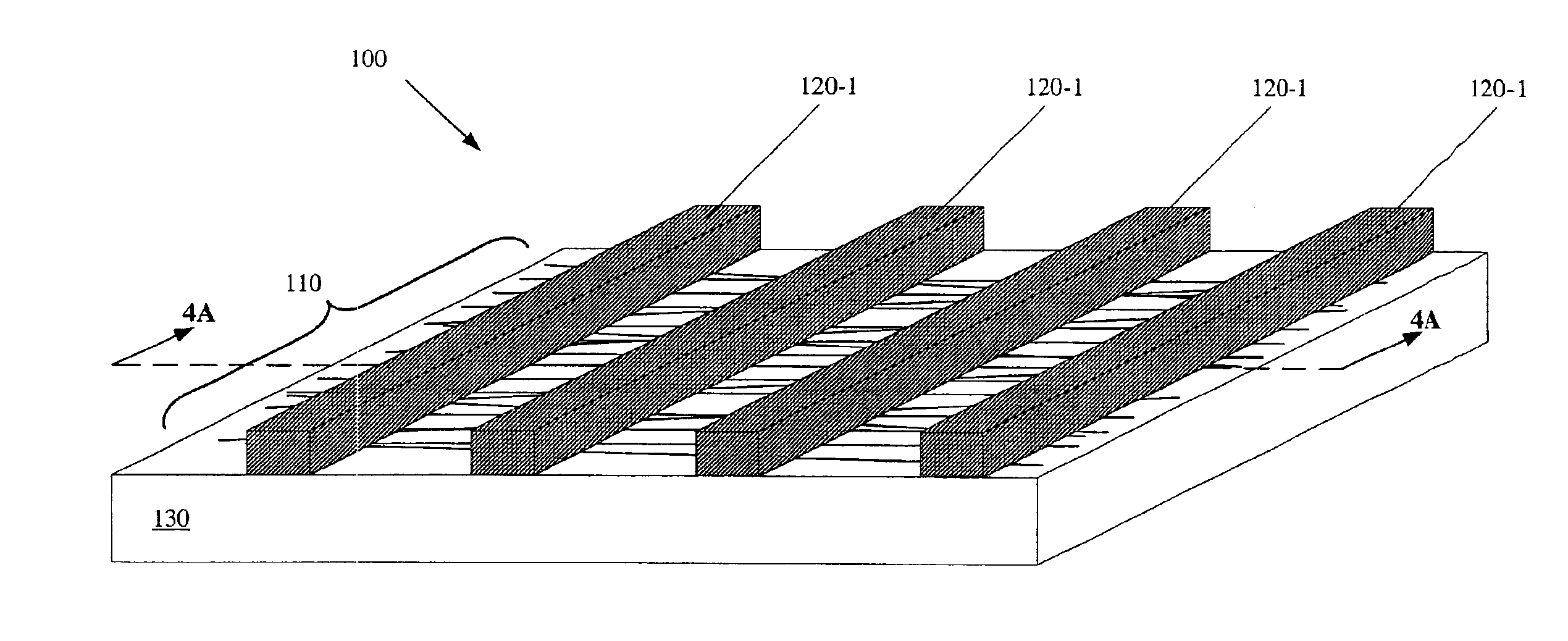
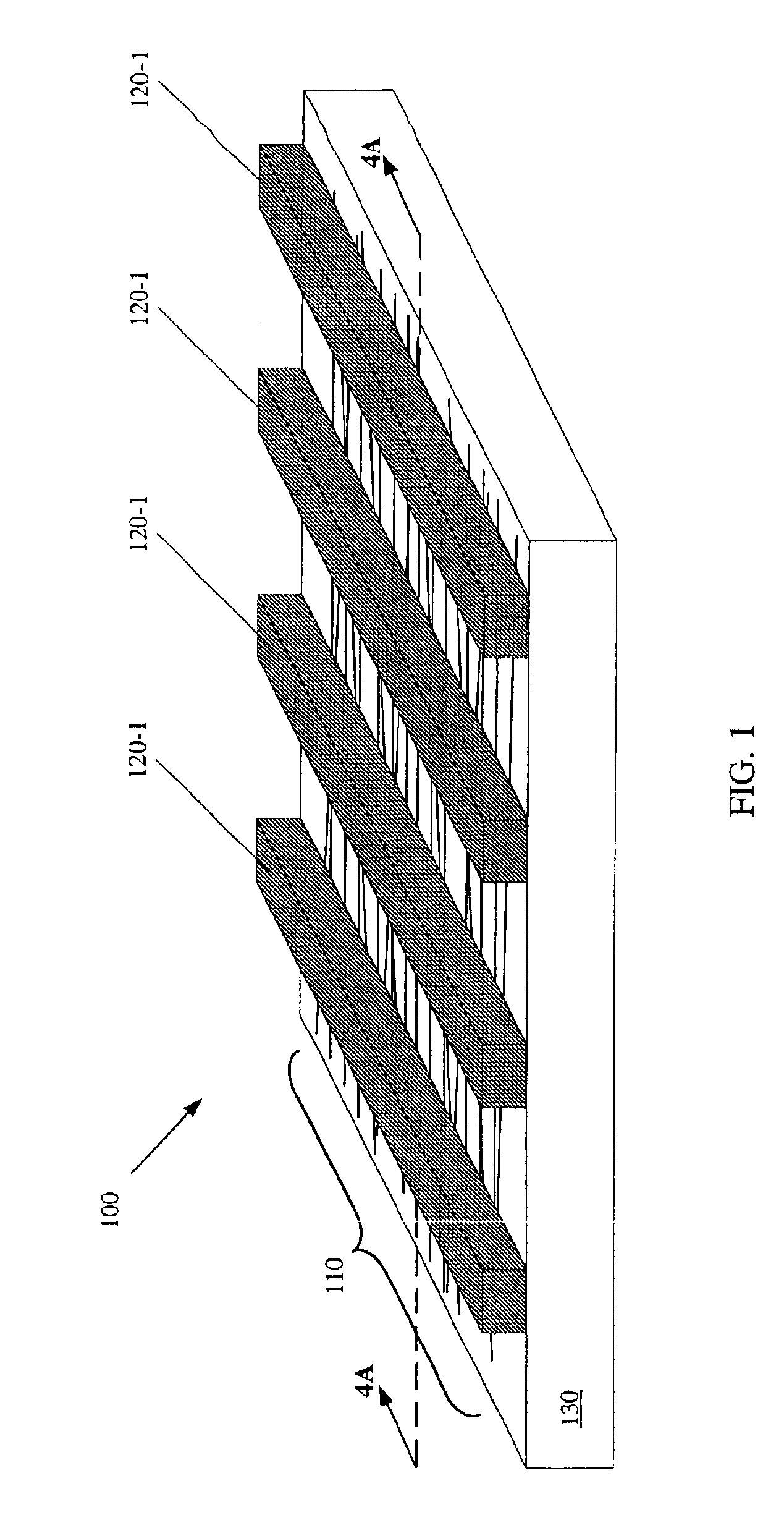
[0038]Carbon nanotubes are usually hollow, elongated structures a few atoms in width with a structure like a sheet of graphite formed into a generally cylindrical configuration. Carbon nanotubes are long molecules, with length to width ratios as large as several thousand or more. They can be formed in furnaces from carbon-containing gases. Carbon nanotubes can form with a single wall, containing just one layer of carbon atoms and having a diameter of one to several nanometers. They can also form with multiple walls, containing a number of hollow cylinders of carbon atoms nested inside one another. They take their name from the nanometer, which is a convenient length for specifying molecular dimensions.

[0039]Other elongated nanostructures have also been developed and named by various researchers. These include nanowires, nanofibers, nanorods, and other structures. Nanostructures having an approximately linear form can be arranged in bundles of structures, such as ropes, braids or twi...


PUM


Abstract

Nanostructure sensing devices for detecting an analyte are described. The devices include nanostructures connected to conductive elements, all on a substrate. Contact regions adjacent to points of contact between the nanostructures and the conductive elements are given special treatment. The proportion of nanostructure surface area within contact regions can be maximized to effect sensing at very low analyte concentrations. The contact regions can be passivated in an effort to prevent interaction between the environment and the contact regions for sensing at higher analyte concentrations and for reducing cross-sensing. Both contact regions and at least some portion of the nanostructures can be covered with a material that is at least partially permeable to the analyte of interest and impermeable to some other species to tune selectivity and sensitivity of the nanostructure sensing device.

Description

DOMESTIC PRIORITY CLAIM[0001]This application claims priority to U.S. Provisional Application No. 60 / 408,412, filed Sep. 4, 2002.BACKGROUND OF THE INVENTION[0002]1. Field of the Invention[0003]The invention is directed generally to nanotube sensors and in particular to nanotube sensors with selective passivation of nanotube-conductor contacts and the nanotubes themselves and methods of forming same.[0004]2. Description of the Related Art[0005]Chemical and biological sensors that use nanotube circuits have been reported in the literature. In general, these sensors include a nanotube or nanotubes in contact with electrodes, thus forming a circuit for current flow. It is generally believed that sensing occurs when analytes interact with the exposed nanotube.[0006]Dai et al. (PCT Publication No. WO 01 / 44796 A1) described a nanotube sensing device which had nanotubes grown from catalyst islands and metal electrodes that covered fully the catalyst islands. The ends of the nanotubes were e...

Claims


Application Information

Patent Timeline
IPC IPC(8): G01N27/414G01N27/403G01N27/12
CPCB82Y15/00G01N27/129Y10S977/734
Inventor BRADLEY, KEITHCOLLINS, PHILIP G.GABRIEL, JEAN-CHRISTOPHE P.GRUNER, GEORGESTAR, ALEXANDER
Owner NANOMIX
Why Eureka
Try Eureka