Method for testing or recording servo signal on perpendicular magnetic recording media

Inactive Publication Date: 2005-05-17
HITACHI LTD
View PDF4 Cites 8 Cited by
  • Summary
  • Abstract
  • Description
  • Claims
  • Application Information

AI Technical Summary

Benefits of technology

[0010]The present invention was devised in light of these problems, and has as an object the provision of a method for the quantitative evaluation of spike noise. This invention has as a further object the automatic detection over a broad range of the media of the effects on pl

Problems solved by technology

In the soft magnetic layer of the perpendicular magnetic recording media, there may exist magnetization states

Method used


Image

  • Method for testing or recording servo signal on perpendicular magnetic recording media
  • Method for testing or recording servo signal on perpendicular magnetic recording media
  • Method for testing or recording servo signal on perpendicular magnetic recording media

Examples


first embodiment

[0062

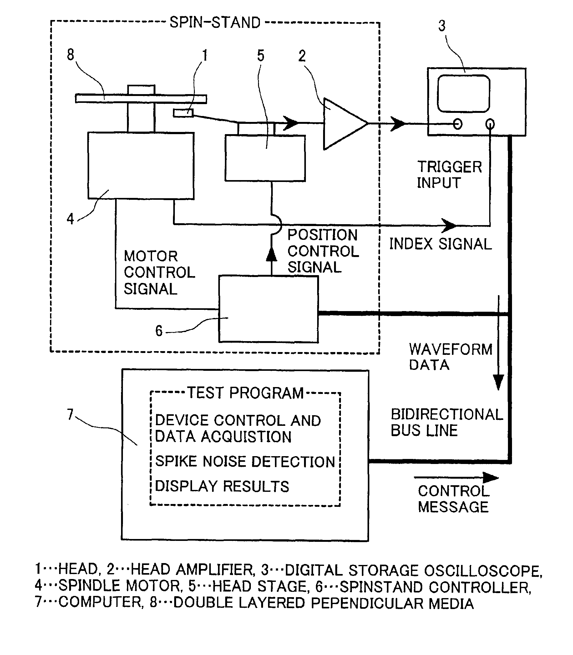
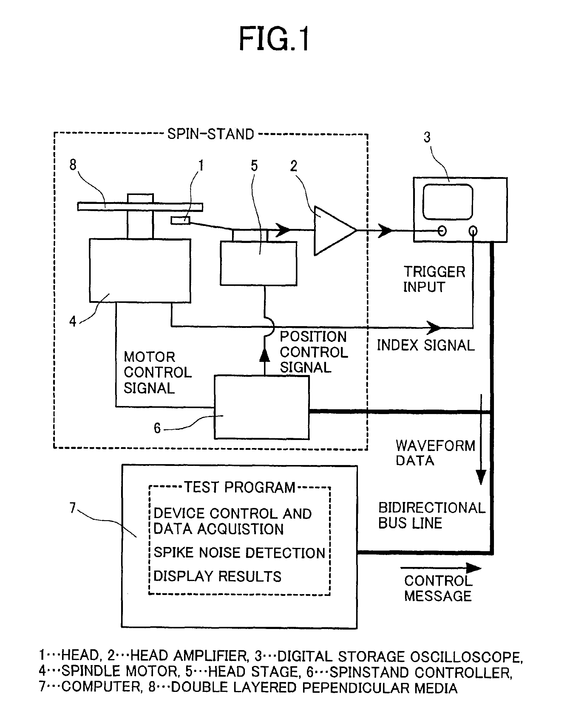
[0063]FIG. 1 is a summary drawing showing one example of perpendicular magnetic recording media testing equipment of this invention. The testing equipment of this example is controlled overall by a computer 7. The computer 7, a digital storage oscilloscope 3, and a spin-stand control device 6 each incorporate a bidirectional bus interface, by which means these devices are interconnected. Of course another connection method, such as for example connections using a serial bus, may also be employed.

[0064]Testing operations are performed according to a test program incorporated in the computer 7. The test program first causes the spindle motor 4 to rotate at a prescribed revolution rate, via the spin-stand control device 6. Then, the head stage 5 is driven to load the head 1 at a prescribed radial position on the double-layer perpendicular magnetic recording media 8. The output signal from the head 1 is amplified by the head amplifier 2, and is input to the input terminal of the di...

second embodiment

[0084

[0085]FIG. 10 is a figure showing in summary another example of inspection equipment used in executing a perpendicular magnetic recording media testing method of this invention. The equipment configuration of this embodiment is the same as in the first embodiment, but this embodiment differs in that a media quality decision function is added to the test program.

[0086]As one of the simplest criteria for decision of quality, a condition for passing might be that the number of spike noise occurrences in a specified radius, or the number of spike noise occurrences within a specified radius range, be less than a fixed number. However, the details and conditions for quality decision will differ depending on the quality standards to be satisfied by the disk. It is possible to set decision conditions by combining the results of analysis functions described in the first embodiment, so that an exceedingly great variety of circumstances can be accommodated. Moreover, consideration is paid...

third embodiment

[0089

[0090]FIG. 12 shows still another example of testing equipment used in executing a perpendicular magnetic recording media testing method of this invention. In this example, the control computer 7 comprises a network interface, and instructions and data can be sent to and received from others computers, measurement equipment, output devices and similar over the network. The test program comprises functions for interpreting and executing external instructions sent from other computers or other devices. Here, external instructions are defined within the test program, and the test program can be instructed to execute or interrupt tests, modify test conditions, and similar. Hence remote operations from other computers over the network are possible. It is not necessary to use a dedicated network interface in configuring a network; the bidirectional bus interface with which the device shown in FIG. 1 is equipped can also be used. Through these features, operations such as the followin...


PUM


Abstract

An object is to automatically detect the positions of spike noise, create a distribution diagram, and perform pass/fail decisions. The cross-correlation function of the signal waveform from a magnetic head 1 and a reference waveform simulating spike noise is used in extraction of spike noise. The number of peaks in the cross-correlation function exceeding a threshold value is counted, and quantitative evaluation of spike noise is performed.

Description

BACKGROUND OF THE INVENTION[0001]1. Field of the Invention[0002]This invention relates to a method for testing perpendicular magnetic recording media, and a method for recording servo signals on perpendicular magnetic recording media.[0003]2. Description of the Related Art[0004]In perpendicular magnetic recording, there exist a mode which uses single-layer perpendicular magnetic recording media, and a mode which uses double-layer perpendicular magnetic recording media. In the latter case, there is the problem of spike noise peculiar to double-layer perpendicular magnetic recording media. Perpendicular magnetic recording media have, below the recording layer comprising a perpendicular magnetization film having a high coercive force to retain information, a soft magnetic layer serving as a return path for the recording magnetic field from the recording head during recording. In general, when there exists a soft magnetic film of size equal to that of the magnetic recording media, a plu...

Claims


Application Information

Patent Timeline
IPC IPC(8): G11B20/24G11B5/73G11B27/36G11B5/00G11B5/012G11B20/10G11B5/62G11B5/02G11B5/84
CPCG11B5/00G11B5/012G11B5/667G11B20/10009G11B27/36G11B20/24G11B2220/20G11B2005/001G11B2005/0029
Inventor KIKUGAWA, ATSUSHITANAHASHI, KIWAMUHONDA, YUKIOFUTAMOTO, MASAAKIHIRAYAMA, YOSHIYUKI
Owner HITACHI LTD
Why Eureka
Try Eureka