Variable-gain amplifier having error amplifier with constant loop gain

a variable-gain amplifier and amplifier technology, applied in differential amplifiers, amplifiers with semiconductor devices/discharge tubes, amplifiers, etc., can solve problems such as not being as simple, and achieve the effect of enhancing the capabilities and/or performance of the disclosed amplifier

Active Publication Date: 2005-05-17
ANALOG DEVICES INC
View PDF4 Cites 63 Cited by
  • Summary
  • Abstract
  • Description
  • Claims
  • Application Information

AI Technical Summary

Benefits of technology

[0012]Many other features are disclosed that, when combined with the basic loop amplifier co

Problems solved by technology

As with many circuits, everything is not as sim

Method used


Image

  • Variable-gain amplifier having error amplifier with constant loop gain
  • Variable-gain amplifier having error amplifier with constant loop gain
  • Variable-gain amplifier having error amplifier with constant loop gain

Examples


Embodiment Construction

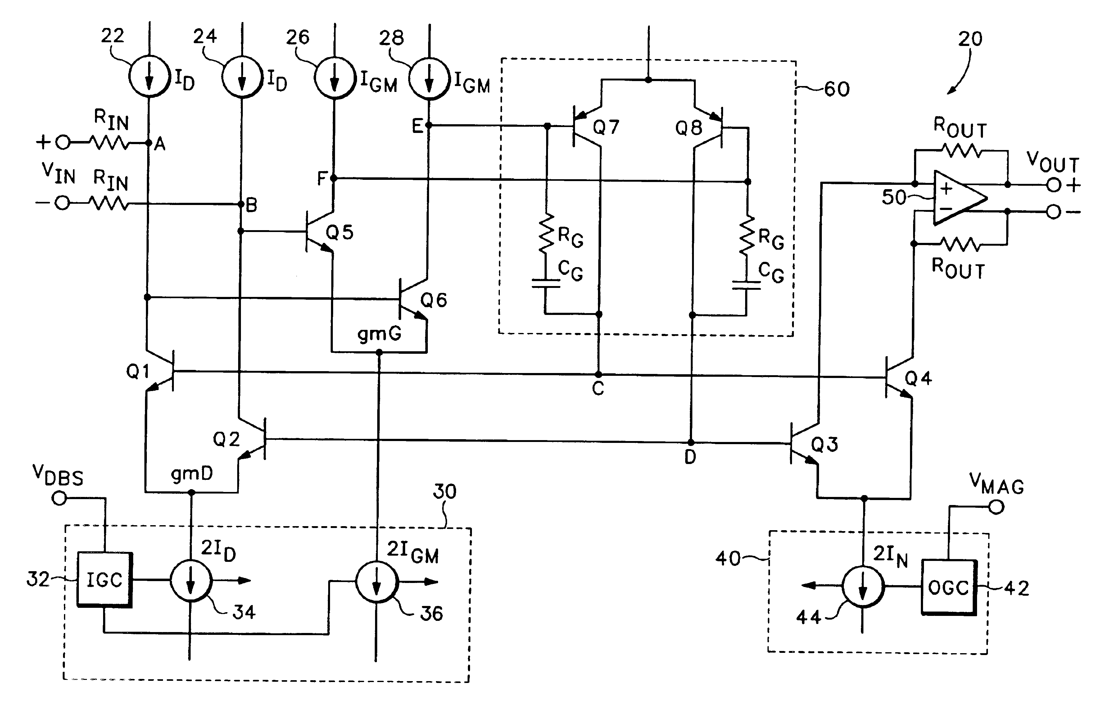
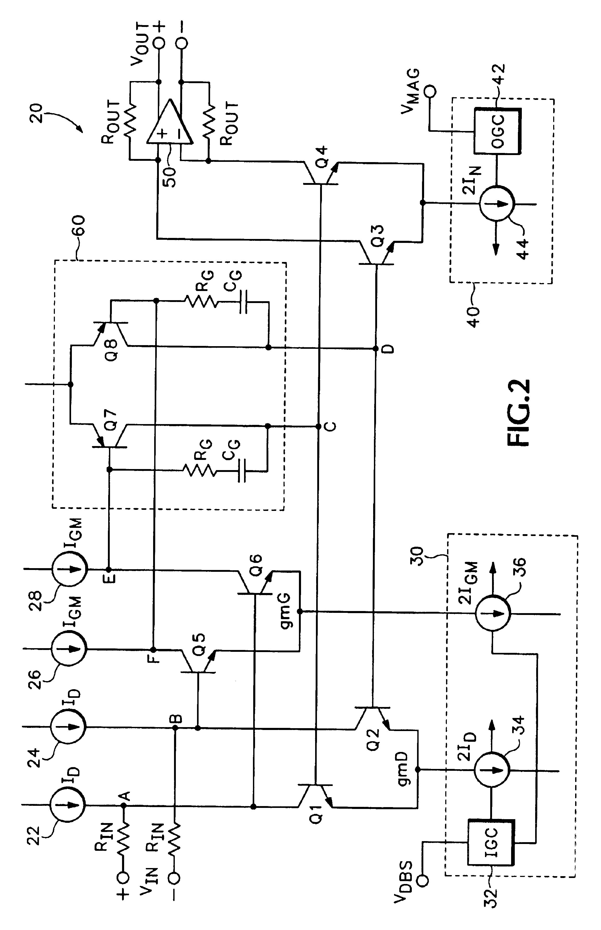
[0023]The preferred embodiments are disclosed below as applied to an amplifier implemented as an integrated circuit using specific combinations of npn and pnp bipolar junction transistors. Those skilled in the art will recognize that the principles taught in the embodiments can also be used in building integrated circuit embodiments using other transistor mixes, and with many different implementations for circuitry peripheral to the amplifier core.

[0024]FIG. 2 shows an amplifier 20 according to a first embodiment of the invention. Four matched npn bipolar transistors are arranged as an input pair Q1, Q2 and an output pair Q3, Q4, with the bases of Q1 and Q4 connected and the bases of Q2 and Q3 connected. The emitters of Q1 and Q2 connect to a controllable input current source 34. The emitters of Q3 and Q4 connect to a controllable output current source 44.

[0025]A differential voltage input VIN is applied through identical input resistors RIN to the collectors of Q1 and Q2 (nodes A a...


PUM


Abstract

A translinear amplifier is disclosed. A loop amplifier drives the bases of the input and output transistor pairs from the differential collector voltage of the input pair. The loop amplifier contains a third differential pair (a gain pair). The tail current of the gain pair is inversely related to the tail current of the input pair, such that loop amplifier gain remains stable when the transconductance of the input pair changes (due, e.g., to input gain changes). In one embodiment, a linear-in-dB interface is provided that adjusts input pair tail current exponentially (and gain pair tail current exponentially and inversely) to linear voltage changes at a gain input.

Description

[0001]This application claims priority from U.S. Provisional Patent Application Ser. No. 60 / 485,830 filed on Jul. 7, 2003 titled, which is incorporated herein by reference.BACKGROUND OF THE INVENTION[0002]1. Field of the Invention[0003]This invention pertains generally to amplifiers, and more particularly to translinear variable-gain amplifiers.[0004]2. Background of the Invention[0005]FIG. 1 illustrates a basic translinear amplifier 10. Translinear refers to the linear dependence of a bipolar transistor's transconductance upon its collector current. Amplifier 10 uses translinear principles to amplify a differential current.[0006]In FIG. 1, amplifier 10 has a first differential transistor pair Q1, Q2 with a current source (having a current magnitude 2ID) regulating their summed tail currents. Amplifier 10 also has a second differential transistor pair Q3, Q4 with a second current source (having a current magnitude 2IN) regulating their summed tail currents. The bases of Q1 and Q4 ar...

Claims


Application Information

Patent Timeline
IPC IPC(8): H03F3/45H03G1/00
CPCH03F3/45H03F3/45085H03G1/0023H03F2203/45466H03F2203/45682H03F2203/45692H03F2203/45566
Inventor GILBERT, BARRIE
Owner ANALOG DEVICES INC
Why Eureka
Try Eureka