Low detection limit turbidimeter

a turbidimeter and detection limit technology, applied in the field of turbidity measurement of solids in suspensions, can solve the problems of stray light diffusely reflected from internal surfaces, the measurement of solids or particles cannot meet the requirements of conventional turbidimeters, and the effect of effective extinguishing the beam and reducing the velocity of the sample flow

Inactive Publication Date: 2005-05-17
HACH CO
View PDF6 Cites 19 Cited by
  • Summary
  • Abstract
  • Description
  • Claims
  • Application Information

AI Technical Summary

Benefits of technology

[0010]In one embodiment, light generated by a source is collimated, or nearly so, by means of a collimating lens and then emitted through the suspension to be measured. The field of the source beam and beam diameter are controlled by the distance of the source from the collimating lens and by the diameter of the source and the collimating lens and optical power of the collimating lens. An equivalent field is imposed on the detector means such that the field of the detector means and field of the source beam coincide at the position of the field stop. The angle separation between the two fields is selected based upon the physical properties of the suspended solids to be measured, such as size of the particles in suspension. Typically 90 degrees is used in the measure of turbidity, as this angle provides a signal least dependent on the size of the particles in suspension. Other angles can be used to advantage, such as 40 or 50 degrees relative to the source beam, to provide a greater sensitivity to the smaller particles in suspension or to increase the path length of detection or overlap between the source beam and the detector field.
[0012]Ideally the source beam is completely extinguished beyond the field of view of the detector, and the detector field of view extends only to the intersection of the source beam and detector field of view and not beyond. In practice, the source beam and the detector field of view interact not only at an area of intersecting fields but also with the internal surfaces of the turbidimeter. Arrangement of the internal surfaces of the turbidimeter within the field of the detector and emitted beam can be used to the advantage of providing light traps for both fields. The light trap for the emitted beam serves to contain internal reflection to within the light trap area and effectively extinguish the beam from radiating as stray light into the field of view of the detector. A light trap may also be provided for the detector field of view to prevent the detector field from extending beyond the light trap area as would otherwise occur from specular reflection of a single interior surface. Thus stray light is effectively reduced for a small volume turbidimeter through extinction of the emitted beam and trapping of the detector field.
[0013]The problem of air bubbles both in suspension and on internal surfaces are effectively mitigated by providing internal surfaces absent of nucleation sites, removal of bubbles prior to entering the sensing area of the turbidimeter, and by providing a sample flow path that sweeps the interior surfaces of the turbidimeter. The sample enters the turbidimeter through the inlet port. Air bubbles are removed from the suspension by providing a chamber on the inlet of the turbidimeter wherein the velocity of the sample flow is reduced allowing the bubbles to separate from the suspension by means of buoyancy. The bubbles that collect at the top of the inlet chamber, or bubble trap, are provided a means of escape through the outlet port of the turbidimeter along with the measured sample suspension. The sample flow, free of suspended bubbles, enters the sensing volume of the turbidimeter through sampling ports in the light traps located at the bottom of the turbidimeter. Both light traps taper from the sampling ports and open out to include the sensing area of the turbidimeter and outlet port. The velocity of the flow increases as the sample passes from the bubble trap area of the turbidimeter into the light trap area, then reduces as the light trap area opens into the sensing volume. The increased velocity of flow in the light trap area maintains the surfaces of the light traps in a condition free of bubbles, solids or sediments that would otherwise impair detection of solids in suspension due to an increase in stray light.

Problems solved by technology

A problem exists in the measure of solids or particles in suspension when the concentration of such particles is low and the size of the particles is small (e.g. 0.05 to 2 μm) in size, as in the detection of an integrity fault or “break-through” in the micro-filtration process of drinking water.
A conventional turbidimeter cannot achieve these requirements.
Stray light that is diffusely reflected from internal surfaces is caused by imperfection in the quality of the surfaces and / or by the presence of air bubbles or other particles that form or adhere to the internal surfaces.
Another cause of poor detection of solids in suspension is illumination of the sample that is unequal to the volume of the sample that falls within the field of view of the detector.

Method used


Image

  • Low detection limit turbidimeter
  • Low detection limit turbidimeter
  • Low detection limit turbidimeter

Examples


Embodiment Construction

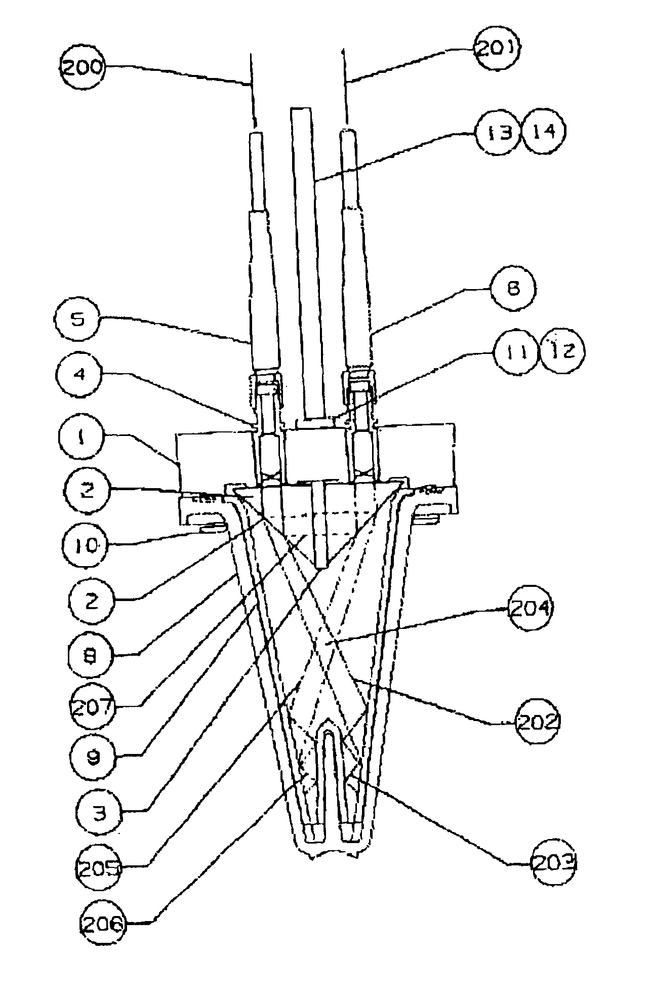
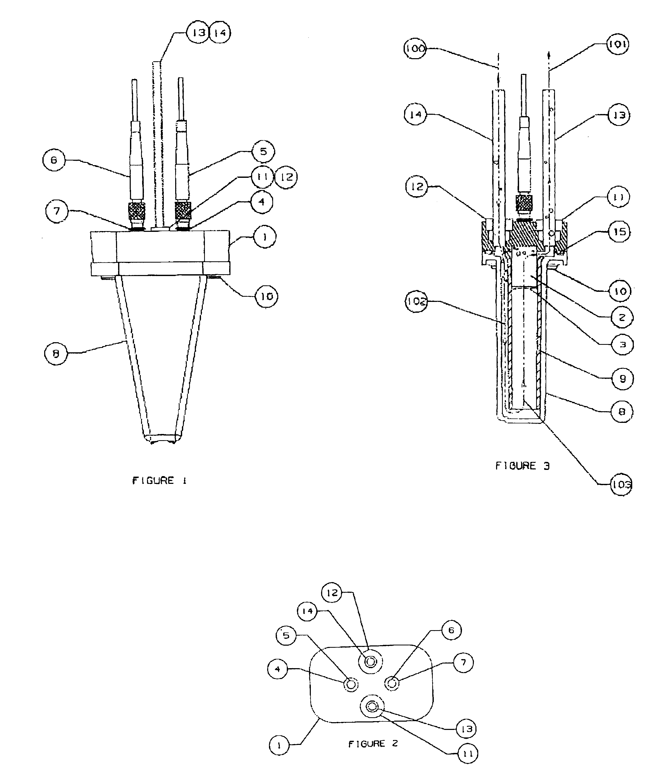
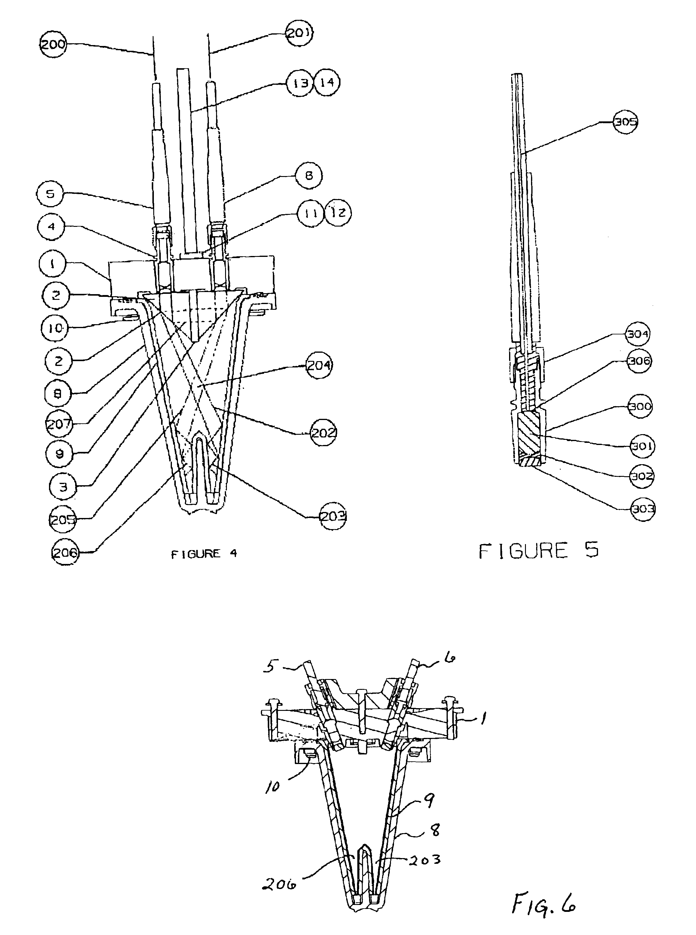
[0020]One embodiment of the present invention is shown in FIGS. 1-5, comprising an optical base 1, right angle prisms 2, optical filter 3, collimate lens assembly 4, focus lens assembly 7 and fiber optic cable assemblies 5 and 6. An outer enclosures, flow diverter 9, retaining screws 10, tubing connectors 11 and 12, sample inlet tube 14 and sample outlet tube 13, and gasket 15 comprise the remaining components of this embodiment of turbidimeter.

[0021]The optical base 1 provides a means to align and position the prisms 2, optical filter 3, and collimating lens assemblies 4 and 7. The right angle prisms 2 and optical filter 3 are bonded together using optical epoxy such as “Epo-Tek 301-2” and attached to the optical base 1 using structural epoxy such as “3M Scotch-Weld 2216 B / A”. The optical filter 3 extends beyond the face of the prisms to prevent stray light from being scattered into the return path 201 in FIG. 4. The collimating lens assemblies are bonded in like fashion to the pri...


PUM

PropertyMeasurementUnit
sizeaaaaaaaaaa
angleaaaaaaaaaa
refractive indexaaaaaaaaaa

Abstract

A turbidimeter having an arrangement of internal surfaces, optical surfaces, and optical restrictions to the field of view of both the illumination and the detector means to significantly improve the lower detection limit of the turbidimeter by reducing the detected signal due to stray light.

Description

CROSS-REFERENCE TO RELATED APPLICATION[0001]This application is based upon, and claims the benefit of, our Provisional Application No. 60 / 375,342, filed Apr. 23, 2002.FIELD OF THE INVENTION[0002]This invention relates to turbidity measurement of solids in a suspension. More particularly, it relates to determination of the concentration of solids in suspension by detection of scattered light caused by the suspended solids.BACKGROUND OF THE INVENTION[0003]A problem exists in the measure of solids or particles in suspension when the concentration of such particles is low and the size of the particles is small (e.g. 0.05 to 2 μm) in size, as in the detection of an integrity fault or “break-through” in the micro-filtration process of drinking water. A typical filter or cartridge used in micro-filtration is composed of a plethora of individual fibers through which the unfiltered or “unfinished” water is passed. In order to assess the integrity of the filter, the effluent water of the filt...

Claims


Application Information

Patent Timeline
Patent Type & Authority Patents(United States)
IPC IPC(8): G01N21/47G01N21/51
CPCG01N21/51G01N2201/0642
Inventor PALUMBO, PERRY A.SCHLEGEL, PAUL D.HUHTA, JEFFREY M.KOLMAN, RICHARD P.
Owner HACH CO
Why Eureka
Try Eureka