Optical amplifier modules

Inactive Publication Date: 2005-05-17
CIENA
View PDF10 Cites 4 Cited by
  • Summary
  • Abstract
  • Description
  • Claims
  • Application Information

AI Technical Summary

Benefits of technology

[0011]According to a fifth aspect of the present invention there is provided, in a wavelength division multiplexed transmission system having an optical transmitter optically coupled with an optical receiver via a transmission path that includes a concatenation of optical amplifier modules having a gain spectrum in which homogeneous broadening is dominant, each containing at least one optical gain-providing region and at least one loss-providing region that provides a loss that is substantially uniform across the gain spect

Problems solved by technology

Whilst small differences in gain may be tolerable, significant differences in gain are common causing degradation to some of the optical signal channels.
However, when the operating gain of the amplifier changes due to a change in the incoming optical signal power, or the demanded optical output power, the resulting change in amplifier gain causes a change in the gain spectrum shape.
As the gain is increased, the amplitude of the broad peak increases unevenly, with the result t

Method used


Image

  • Optical amplifier modules
  • Optical amplifier modules
  • Optical amplifier modules

Examples


Embodiment Construction

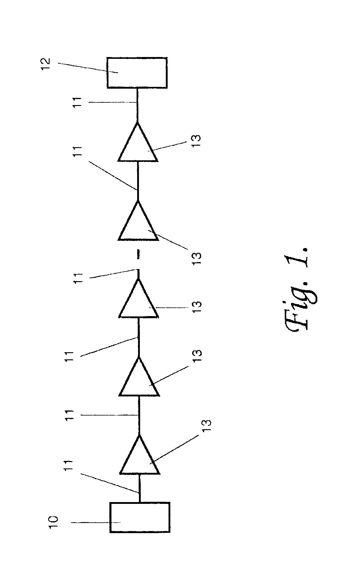
[0019]The transmission system of FIG. 1 comprises a WDM transmitter 10 typically arranged to launch a plurality of optical signals that are wavelength division multiplexed into one end of an optical fibre transmission path 11. At the far end of this path these signals are detected by a WDM receiver 12. At spaced intervals along the transmission path 11 are inserted a set of optical amplifier modules 13. Each optical amplifier module 13 includes at least one optical gain providing optically pumped rare-earth doped optical fibre amplifier.

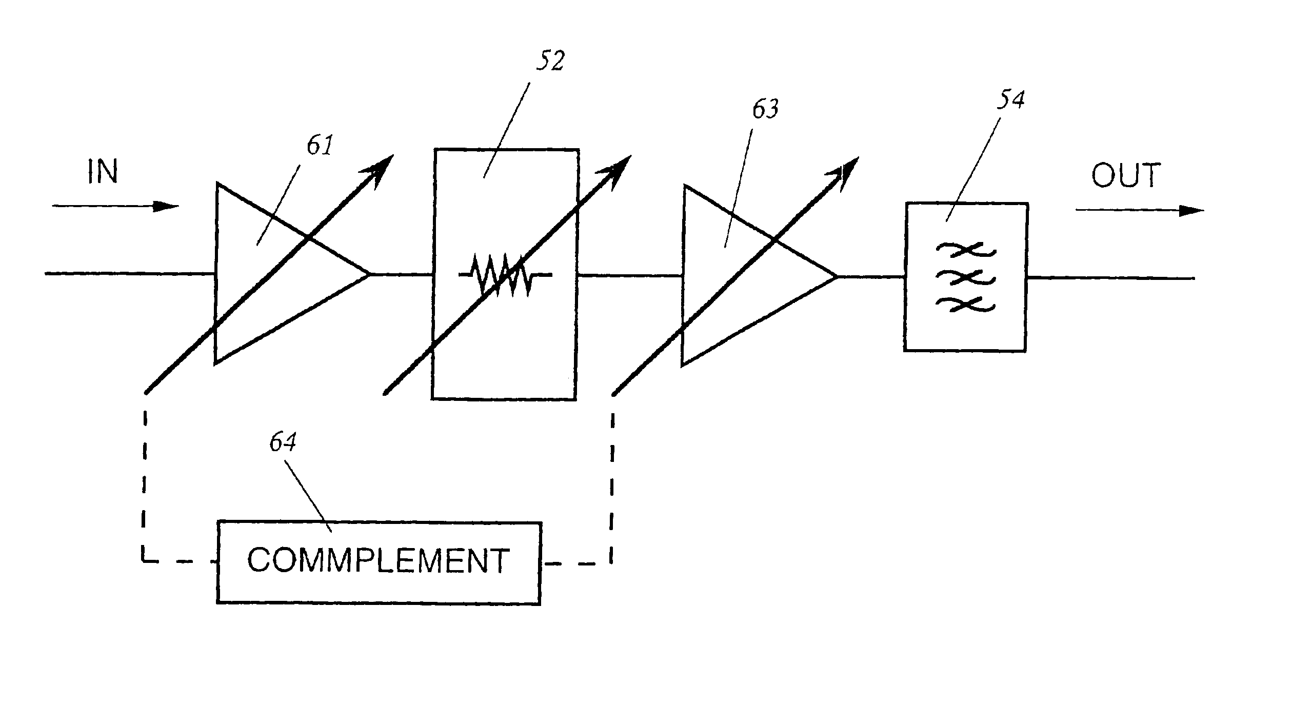
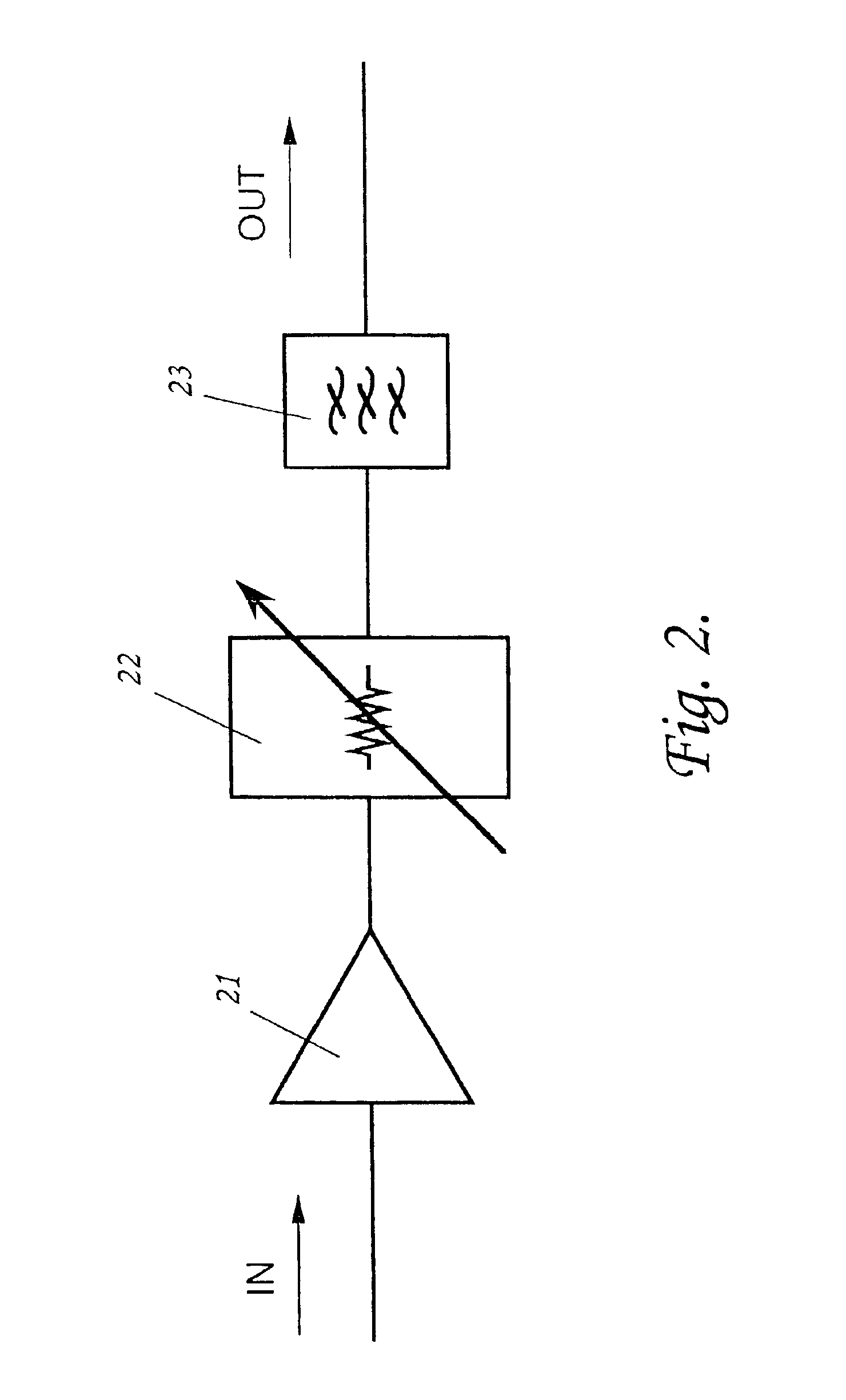
[0020]The basic elements of a first preferred form of an amplifier module 13 of FIG. 1 is depicted in FIG. 2, and comprises a fixed gain rare-earth doped optical waveguide optical amplifier 21 and an electronically controllable variable attenuation optical attenuator 22. FIG. 2 shows the attenuator 22 located downstream of the amplifier 21, but alternatively it may be located upstream of it. Additionally the modulator 13 typically includes a passive ...


PUM


Abstract

A variable gain optical amplifier, in which homogeneous gain broadening is dominant, has first and second fixed gain rare-earth doped optical waveguide amplifiers (21, 23) optically in series together with an intervening variable attenuation optical attenuator (22). This arrangement circumvents the problem of gain tilt encountered when operating such amplifiers under variable gain conditions. An alternative form of the module has variable gain waveguide amplifiers, but these are co-regulated so that the aggregate of their gain at a wavelength within the gain spectrum is maintained constant. A further alternative form of module is employed in a concatenation of such modules. In such a concatenation, the gain of individual modules is allowed to vary, but the aggregate of the gain, at a wavelength within the gain spectrum, of all the waveguide amplifiers of all the modules of the concatenation is maintained constant.

Description

RELATED APPLICATION[0001]This application is a continuation of U.S. patent application Ser. No. 09 / 214,248, now U.S. Pat. No. 6,493,682 filed Sep. 20, 1999, which is the national filing of international application number PCT / GB97 / 01701 filed Jun. 25, 1997.BACKGROUND OF THE INVENTION[0002]This invention relates to optical amplifier modules in which homogeneous gain broadening is dominant, such as modules incorporating optically pumped rare-earth doped optical waveguide amplifiers.[0003]Such optical amplifiers have an optical gain spectrum that varies with wavelength. The gain spectrum also depends on the operating conditions of the particular amplifier. To be more precise, for a fixed amplifier configuration, the gain spectrum will depend on the gain of the amplifier. In an optical communication system using multiple wavelengths for the transmission of data, the gain spectrum of the amplifier results in different signal channels having a different optical gain. Whilst small differen...

Claims


Application Information

Patent Timeline
IPC IPC(8): H04B10/17H01S3/10H04J14/00H04B10/291H04B10/294H04J14/02
CPCH01S3/10023H04B10/291H04B10/2941H04B10/2912H04B2210/003
Inventor JOLLEY, NIGEL EDWARDDAVIS, FIONAEPWORTH, RICHARD EDWARD
Owner CIENA
Why Eureka
Try Eureka