Packet-based optical communications networks

a packet-based optical and communication network technology, applied in the field of optical communication networks, can solve the problems of limiting the data handling rate within optical networks, complex and expensive implementation, and so as to achieve the effect of reducing the overhead associated with overhead and increasing the data ra

Inactive Publication Date: 2005-05-17
CIENA
View PDF5 Cites 18 Cited by
  • Summary
  • Abstract
  • Description
  • Claims
  • Application Information

AI Technical Summary

Benefits of technology

[0010]This header structure enables the clock pulses in the first section to be used to control the timing instants when the header information in the second section is read. The header information can thus be read using the data in the header alone, without needing to alter the structure of the packet payload. The clock pulses can be delayed in order to enable them to be used to control the reading of data in the second section of the packet header.
[0012]The duration of the first section may be equal to the duration of the second section, so that the first section can be delayed to correspond in timing to the second section. Alternatively, the duration of the second section can be an integer multiple of the duration of the first section, so that the first section can be delayed a number of times to cover the second section. This enables a shorter first section of clocking data to be used, reducing the overhead associated with it.

Problems solved by technology

The conversion of high data rate optical signals into the electrical domain and the processing of such signals provides difficulties and may limit the data handling rates within optical networks.
However, this conversion and processing can be required for performing switching and routing functions, and is recognised as causing a restriction.
One proposal involves the use of time-shift keying, but the fine tolerances in timing and delay compensation present serious difficulties.
One particular problem which arises in asynchronous transmission, such as packet-based transmission, is deriving a clock signal to enable decoding of the packet data.
This may be achieved using burst mode receivers or over-sampling receivers, but these are complex and expensive to implement.
A problem with this approach is the long time taken to synchronise the clock extraction circuit, corresponding to many bits of the data structure.
A problem with this approach is that the packet payload is distorted, and the packet header is no longer a separate part of the packet structure.

Method used


Image

  • Packet-based optical communications networks
  • Packet-based optical communications networks
  • Packet-based optical communications networks

Examples


Embodiment Construction

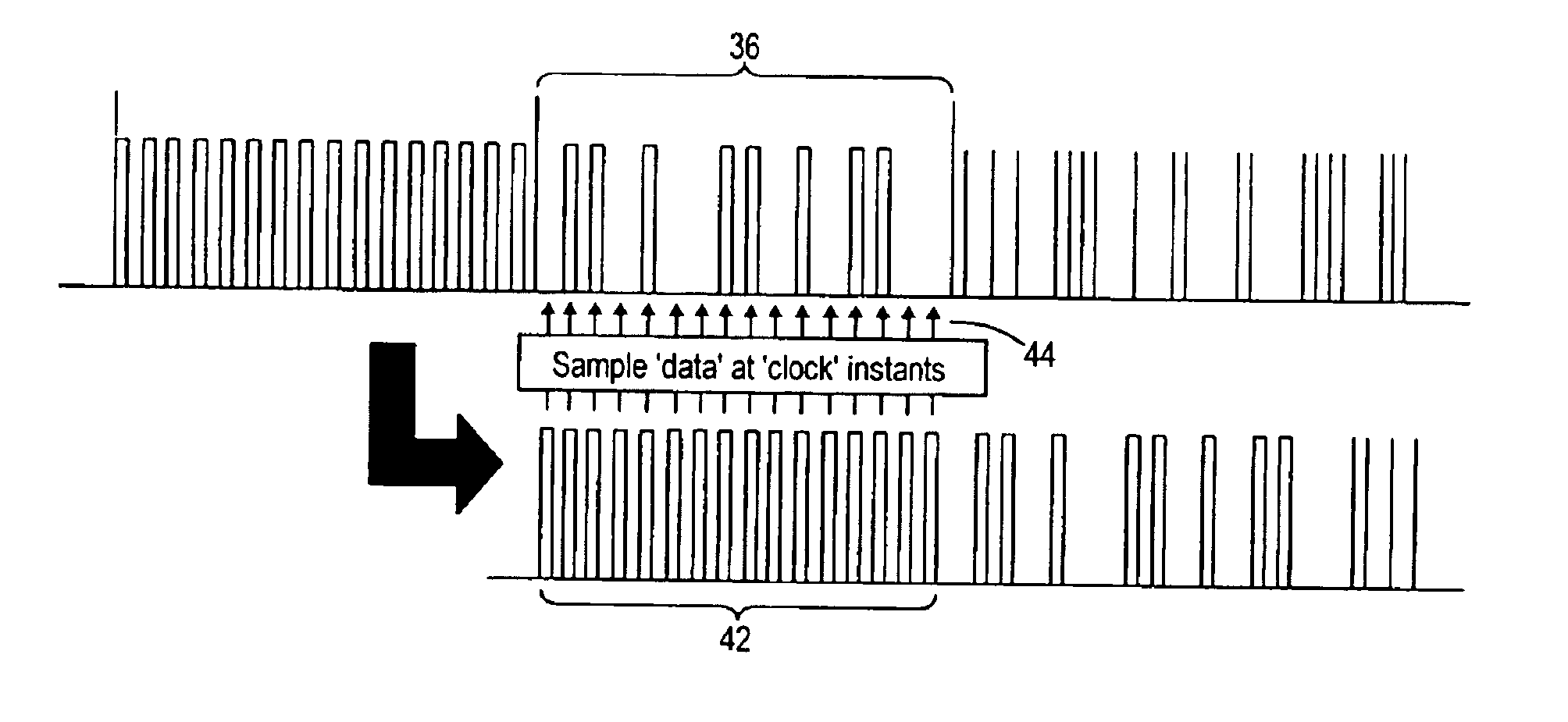
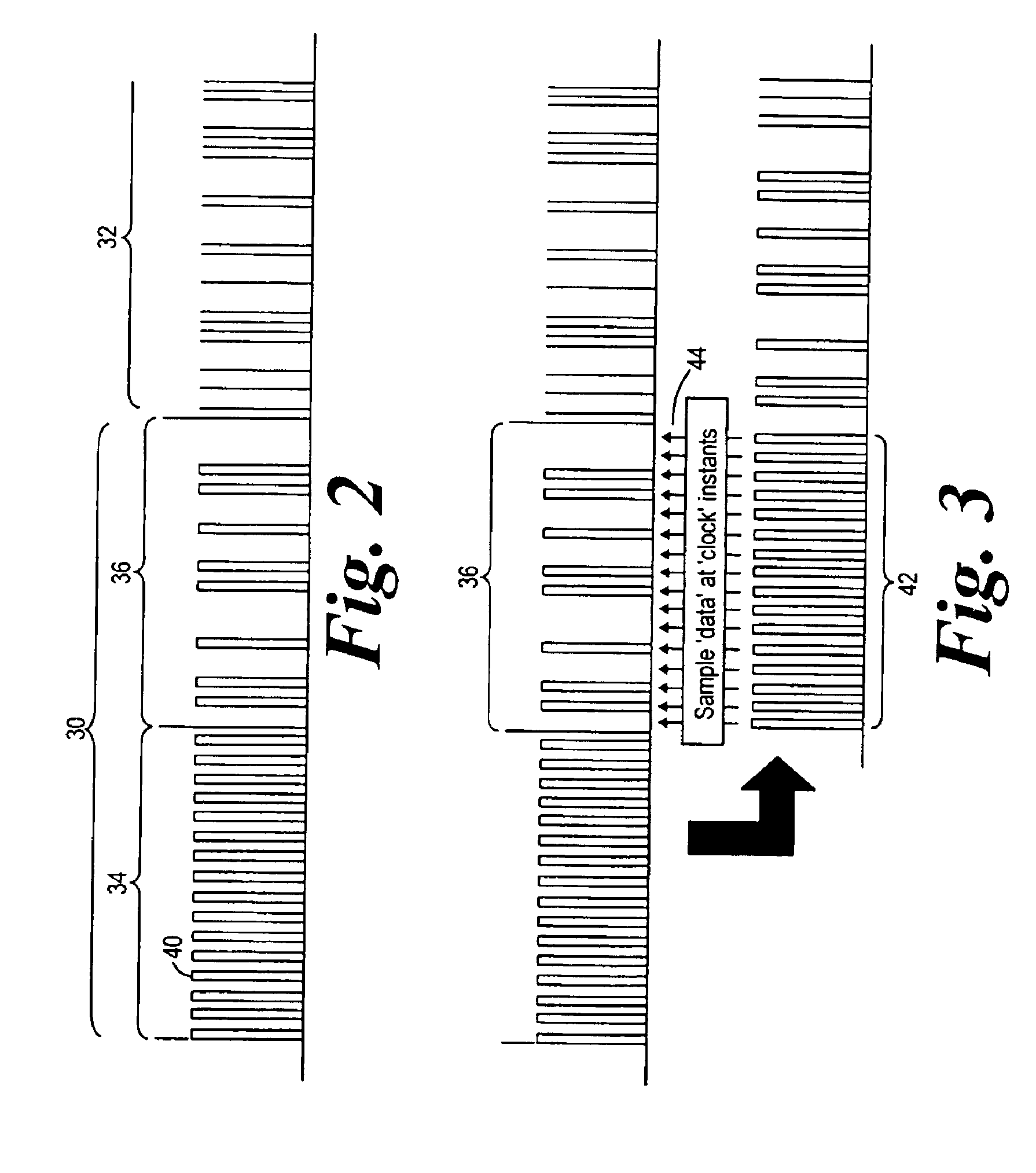
[0047]This invention relates to the encoding of data to form an optical packet, and to apparatus for reading the header (or label) of the packet. The invention therefore relates to the physical layer of an optical packet network. This physical layer may be used to implement any desired packet switching mechanism and furthermore, as will be apparent from the following, it does not provide any constraints on the nature or encoding of the payload data within the optical packets. The packet reading and writing system may therefore be used to implement an optical packet based switching network, for example a label based switched network.

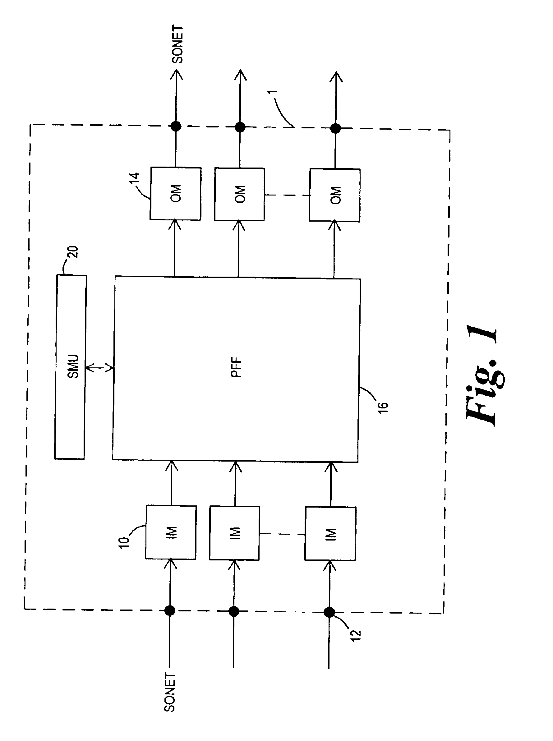
[0048]For the purposes of explanation, the operation of a conventional label switch operating in an optical network will be explained with reference to FIG. 1.

[0049]The fundamental operation of the switching system is to route packets according to information in the label of the packet. As will be known by those skilled in the art, the label contains all ...


PUM


Abstract

A structure for an optical packet for transmission over an optical network comprises a packet header (30) and a packet payload (32). The header comprises first and second sections (34, 36). The first section (34) comprises a series of clock pulses (40) at the data rate of the second section of the packet header, or a multiple or sub-multiple thereof. This header structure enables the clock pulses in the first section (34) to be used to control the timing instants when the header information in the second section (36) is read. The header information can thus be read using the data in the header alone, without needing to alter the structure of the packet payload. The clock pulses can be delayed in order to enable them to be used to control the reading of data in the second section of the packet header. The invention ca be used in optical communications networks.

Description

FIELD OF THE INVENTION[0001]This invention relates to the field of optical communication networks, and in particular to the processing of packet-based optical signals and to the information stored in the packet headers of such signals.BACKGROUND OF THE INVENTION[0002]The advantages of packet-based networks are well known. Such systems allow more flexible and efficient use of bandwidth than circuit switched systems.[0003]The recent rapid increase in transmission capacity achieved by optical transmission systems far exceeds the improvements in electronic processing speeds. The conversion of high data rate optical signals into the electrical domain and the processing of such signals provides difficulties and may limit the data handling rates within optical networks. However, this conversion and processing can be required for performing switching and routing functions, and is recognised as causing a restriction.[0004]There have been proposals which provide all-optical networks in which ...

Claims


Application Information

Patent Timeline
Patent Type & Authority Patents(United States)
IPC IPC(8): H04L7/04H04L7/06
CPCH04L7/041H04L7/06H04L7/046
Inventor FICE, MARTYNKING, JONATHAN
Owner CIENA
Why Eureka
Try Eureka