
Overspeed control system for gas turbine electric powerplant

a technology of electric power plants and control systems, applied in position/direction control, analog and hybrid computing, structural/machine measurement, etc., can solve the problems of increased power consumption, increased cost, and increased difficulty in adjusting the speed of the turbine engine, and achieve the effect of slowing down the turbine engin

Inactive Publication Date: 2005-05-17
ALTEK POWER CORP
View PDF23 Cites 45 Cited by
  • Summary
  • Abstract
  • Description
  • Claims
  • Application Information

AI Technical Summary

Benefits of technology

"The present invention is a gas turbine engine powerplant that uses a gas turbine engine to operate an electric generator. The system ensures that the speed of the turbine engine does not exceed a safe limit, even if the load on the engine is dropped. This allows the powerplant to operate safely in an unattended condition. The powerplant can be used in remote areas or for backup power, and it can also be used as a source of co-generation electric power or distributed power generation. The powerplant is portable, and it can be easily moved to different locations. The control system of the powerplant ensures automatic start-up and operation when high demand is reached, and it can also be shut down as needed. The powerplant can provide a cost-effective solution for producing electric power, and it can be used as a source of co-generation or distributed power generation to meet growing demand or to avoid high costs."

Problems solved by technology

Such operations may require more power than can be supplied by typical gas or diesel generators.
For example, in the above-described remote drilling operation, utility power may be available, but the cost may be prohibitive based on the short period of time during which electric power will be required.
Such a situation may also occur during large-scale, remote construction projects.
Utilities commonly struggle with the problem of meeting peak demand, which occurs typically at particular times of the day, and is usually more severe during certain times of the year.
To meet peak demand, power plants must typically be overdesigned—meaning that they only run near peak efficiency during periods of high demand.
Therefore, for the majority of a given day, the power plant runs at a reduced output and, unfortunately, a lower efficiency.
For example, it is common for large industrial facilities to limited in the amount of power they may use, or to otherwise be charged a significantly elevated price during periods of high demand.
Such may occur, for example, during periods of extreme weather, when the general consumption of electric power typically increases.
Many times, the provider of electric power does not have the capacity to meet the increased demand.
The first utility may be at a disadvantage, because the cost to purchase and transfer the electric power to the area of demand may be high.
Because of the high rotational speed of the gas turbine engine, should the load connected thereto be suddenly removed, such as due to, for example, a broken coupling, a gearbox failure, or other causes, the rotational speed of the gas turbine engine could quickly exceed safe operating limits.
Thus, a sudden and unexpected removal of the load will often cause the turbine engine to enter what is commonly referred to as an “overspeed” or “runaway” condition.
If nothing is done to slow the turbine engine, the result of such a condition may be the failure of the engine and possibly other components connected thereto.
More catastrophically, the high rotational speeds that may result, can cause the turbine engine to disintegrate, destroying the engine and endangering persons and other equipment in the area.

Method used


Image

  • Overspeed control system for gas turbine electric powerplant
  • Overspeed control system for gas turbine electric powerplant
  • Overspeed control system for gas turbine electric powerplant

Examples


Embodiment Construction

)

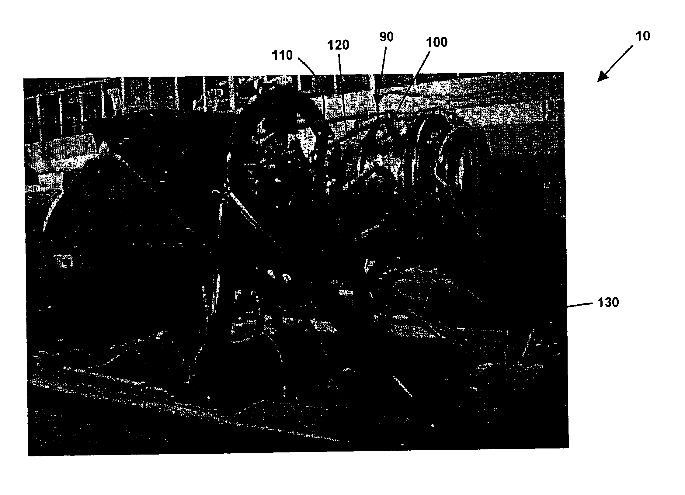
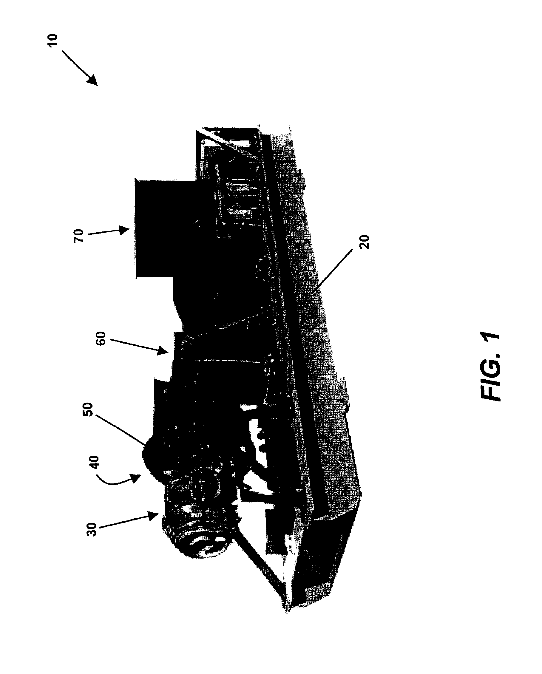
[0025]An isometric view of one embodiment of a gas turbine electric powerplant 10 of the present invention can be observed in FIG. 1. The gas turbine electric powerplant 10 preferably resides on a unitary base, such as the skid 20 shown. In this manner, the entire gas turbine electric powerplant 10 can be easily and conveniently transported to virtually any location requiring electric power production. It is also possible, however, to assemble the gas turbine electric powerplant 10 onto a fixed mounting surface, such as, for example, the floor of a factory.

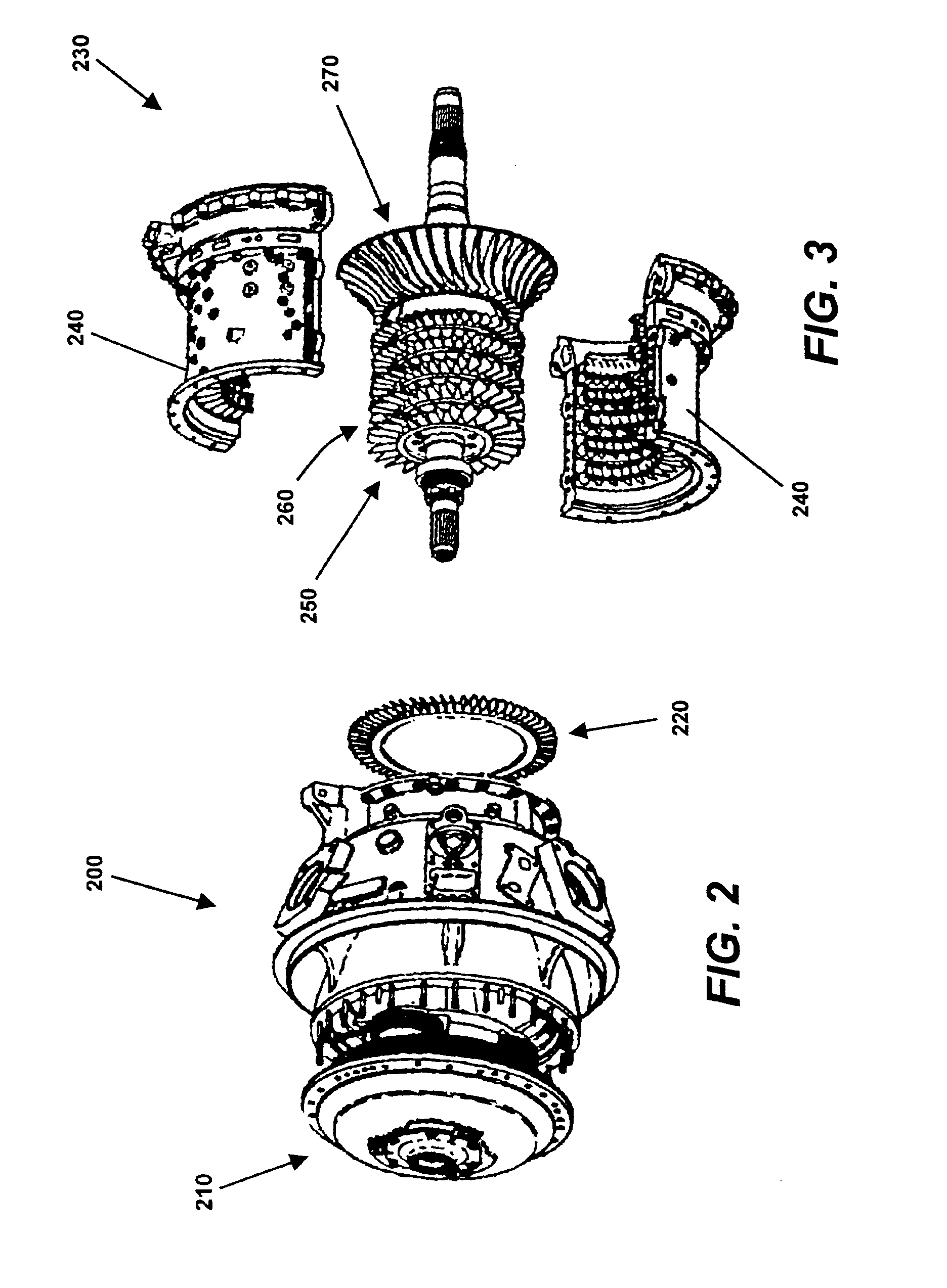
[0026]The gas turbine electric powerplant 10 is shown to be powered by a gas turbine engine 30, which can be better observed by reference to FIGS. 2-7. The gas turbine engine 30 may be aeroderivative, such as is intended for use in a helicopter or other aircraft. Preferably, the gas turbine engine 30 is a turboshaft engine, wherein an output shaft connected to a power turbine within the engine is provided for coupling to an exter...


PUM


Abstract

A turbine overspeed control system for a gas turbine electrical powerplant. The powerplant may employ an aeroderivative gas turbine engine for producing electrical power. The overspeed control system preferably comprises a compression relief system and an air directing system. When an overspeed condition of the gas turbine engine is detected, the compression relief system acts to remove air from a combustion section of the engine. Preferably, the air is removed to the atmosphere. The air directing system operates to ensure that air entering a compressor section of the gas turbine engine does not impinge on the blades of a compressor turbine located therein at the optimum angle. The result of operating the compression relief and air directing systems is a reduced combustor efficiency. Consequently, a reduced amount of hot gases are available to drive the turbines of the gas turbine engine, and the rotational speed thereof decreases.

Description

BACKGROUND AND SUMMARY OF THE INVENTION[0001]The present invention relates to a gas turbine electric powerplant, and more particularly to a system for controlling a turbine engine used to operate the powerplant. The powerplant uses a turbine engine, such as an aircraft engine, to operate an electric generator that produces electric power. The system of the present invention ensures that the speed of the turbine engine will not exceed a safe limit should the load on the turbine engine be dropped. The system of the present invention allows the powerplant to be operated safely in an unattended condition.[0002]There are numerous situations wherein it may be desirable to use a powerplant of the present invention. For example, it may be necessary to provide electrical power to a remote area that is not supplied by a utility company. Electric power consuming: operations that are commonly conducted in remote areas include, for example, drilling for oil and natural gas. Such operations may r...

Claims


Application Information

Patent Timeline
Patent Type & Authority Patents(United States)
IPC IPC(8): G06F11/00F02C9/18
CPCF02C9/18Y10T477/40F05D2270/021
Inventor MUNSON, JR., BILL C.
Owner ALTEK POWER CORP
Learn More