
Multicore DSP device having shared program memory with conditional write protection

a multi-core dsp and write protection technology, applied in the field of digital signal processors, can solve problems such as write protection interference, interference with the operation of other processor cores,

Inactive Publication Date: 2005-05-17
TEXAS INSTR INC
View PDF6 Cites 47 Cited by
  • Summary
  • Abstract
  • Description
  • Claims
  • Application Information

AI Technical Summary

Benefits of technology

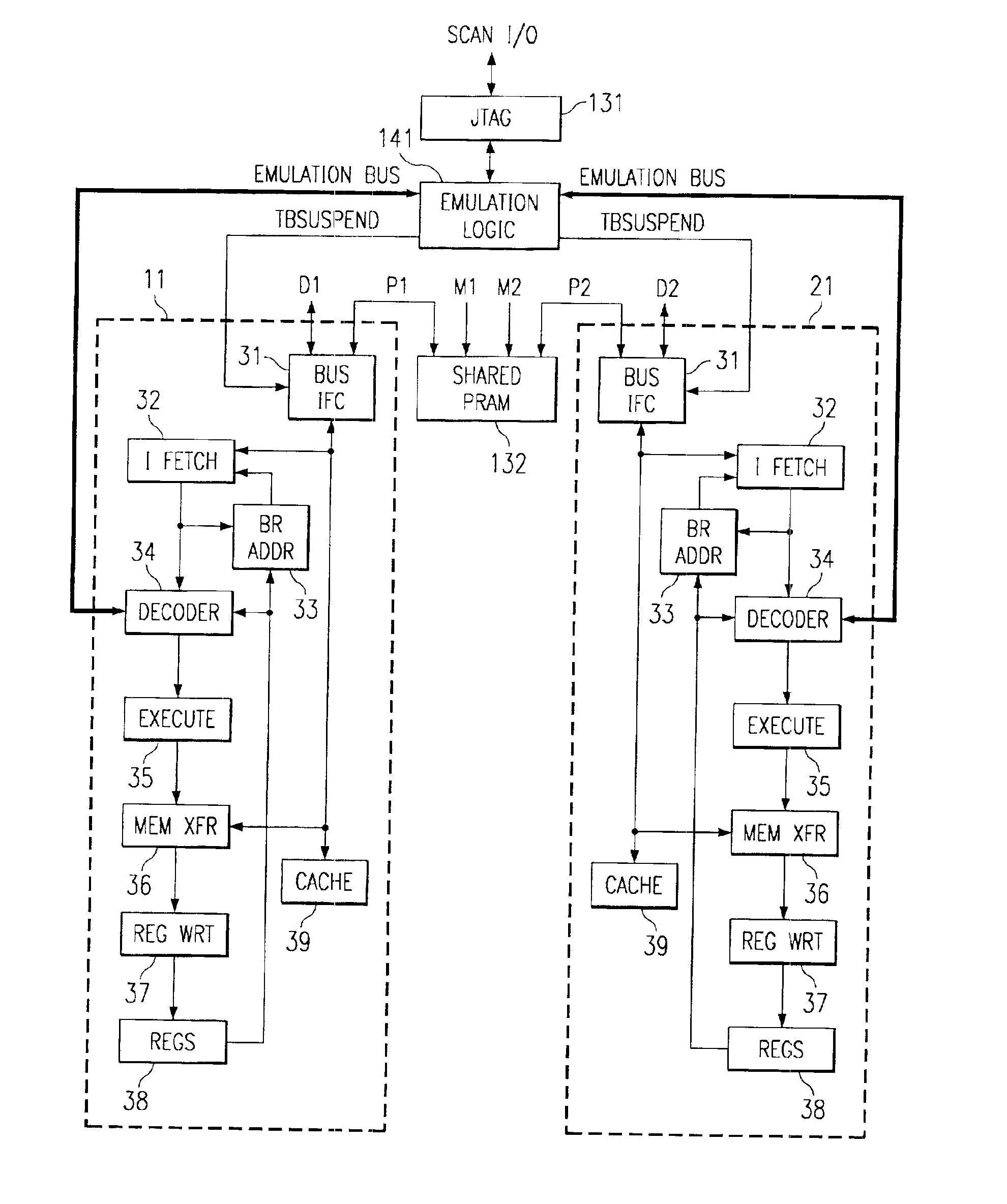
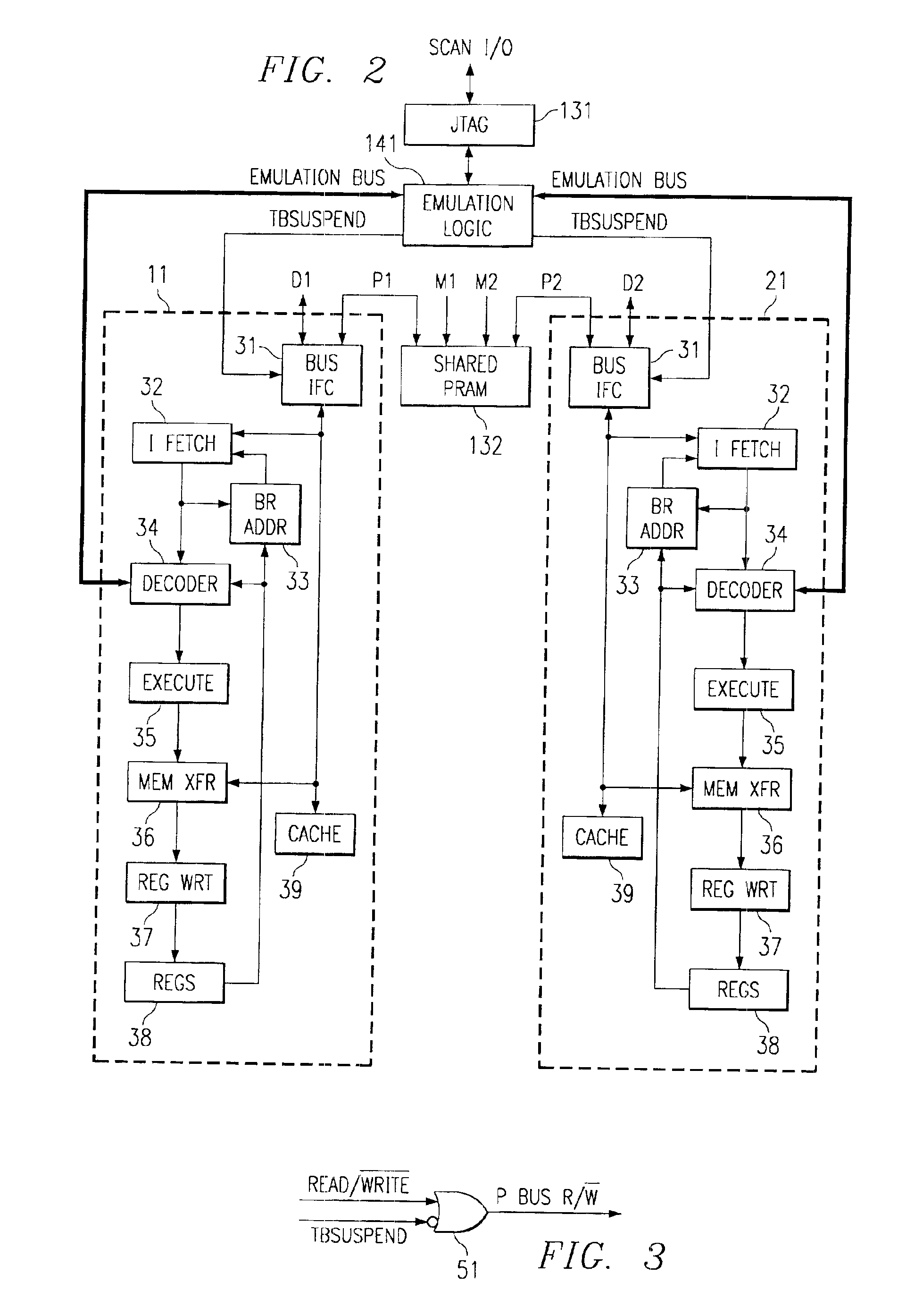
[0008]Accordingly, the present invention contemplates a multi-core digital signal processor having a shared program memory with conditional write protection. In one embodiment, the digital signal processor includes a shared program memory, an emulation logic module, and multiple processor cores each coupled to the shared program memory by corresponding instruction buses. The emulation logic module preferably determines the operating modes of each of the processors, e.g., whether they are operating in a normal mode or an emulation mode. In the emulation mode, the emulation logic can alter the states of various processor hardware and the contents of various registers and memory. The instruction buses each include a read / write signal that, while their corresponding processor cores are in normal mode, is maintained in a read state. On the other hand, when the processor cores are in the emulation mode, the processor cores are allowed to determine the state of the instruction bus read / write signals. Each instruction bus read / write signal is preferably generated by a logic gate that prevents the processor core from affecting the read / write signal value in normal mode, but allows the processor core to determine the read / write signal value in emulation mode. In this manner, the logic gate prevents write operations to the shared program memory when the emulation logic de-asserts a signal indicative of emulation mode, and allows write operations to the shared program memory when the emulation logic asserts the signal indicative of emulation mode. The logic gate is preferably included in a bus interface module in each processor core.

Problems solved by technology

However, because the shared program memory is writeable, a processor core in a runaway condition could conceivably corrupt the software, thereby interfering with the operation of other processor cores.
Furthermore, write protection would interfere with a desirable verification technique in which the processor itself writes test software to program memory.

Method used


Image

  • Multicore DSP device having shared program memory with conditional write protection
  • Multicore DSP device having shared program memory with conditional write protection
  • Multicore DSP device having shared program memory with conditional write protection

Examples


Embodiment Construction

[0014]The preferred embodiment of the present invention is discussed below in the context of a multi-core, fixed-point, digital signal processor (DSP) chip. This embodiment, however, is not intended to limit the scope of this disclosure to this context, rather, the preferred embodiment may have applicability to any multiple core DSP device that would benefit conditional write protection of a shared program memory.

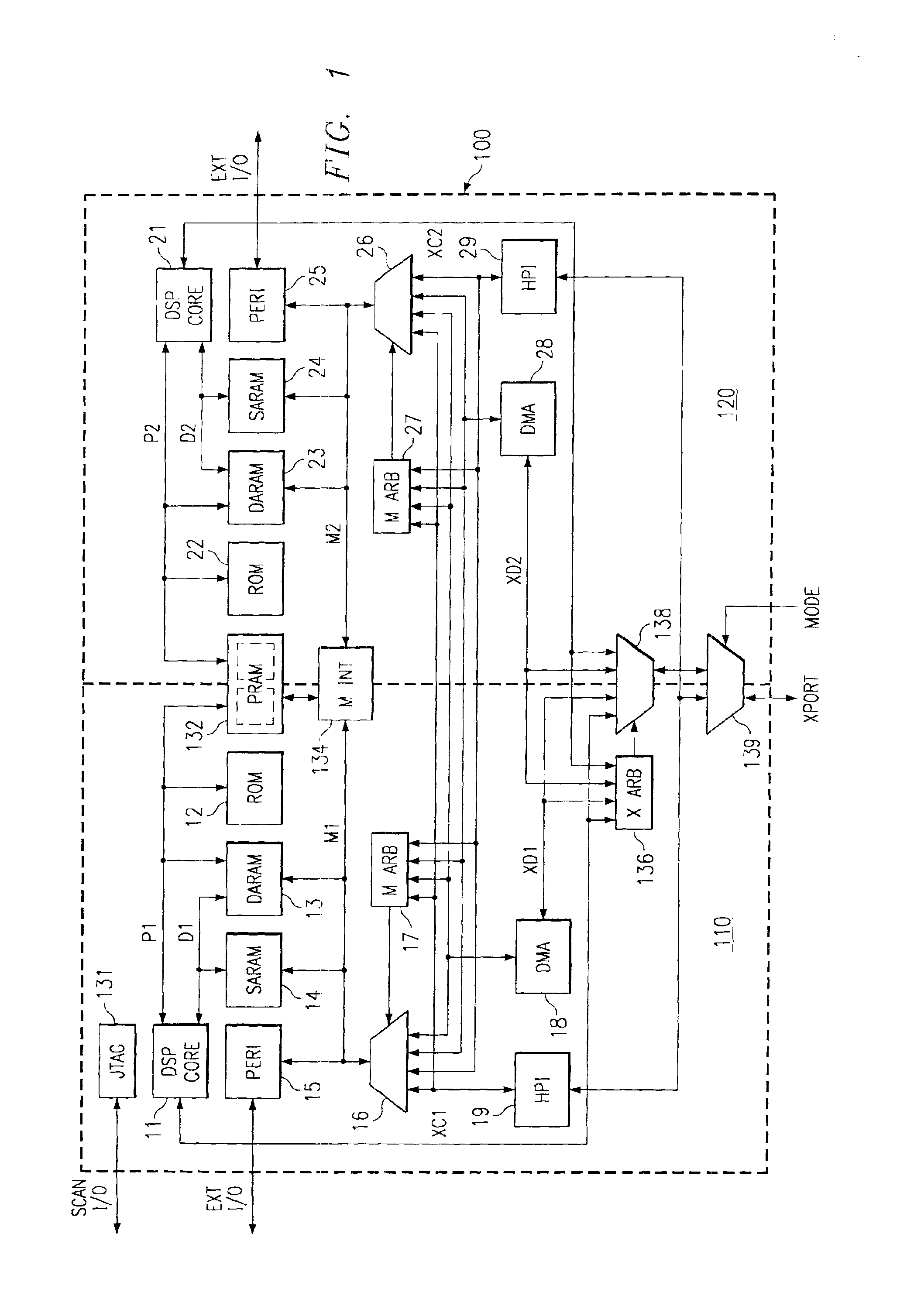
[0015]Turning now to the FIG. 1 shows a DSP chip 100 that includes multiple DSP subsystems 110, 120, a shared program memory (PRAM) 132, a memory bus interface 134, an external I / O port (XPORT) arbiter 136, an XPORT multiplexer 138, and a host port interface (HPI) multiplexer 139. Each DSP subsystem 110, 120 (generally separated by the dashed line in FIG. 1) preferably includes a DSP core 11, 21, a read-only memory (ROM) 12, 22, a dual-access, random access memory (DARAM) 13, 23, a single-access, random access memory (SARAM) 14, 24, one or more peripheral devices 15, 25, an...


PUM


Abstract

A multi-core digital signal processor is disclosed having a shared program memory with conditional write protection. In one embodiment, the digital signal processor includes a shared program memory, an emulation logic module, and multiple processor cores each coupled to the shared program memory by corresponding instruction buses. The emulation logic module preferably determines the operating modes of each of the processors, e.g., whether they are operating in a normal mode or an emulation mode. In the emulation mode, the emulation logic can alter the states of various processor hardware and the contents of various registers and memory. The instruction buses each include a read / write signal that, while their corresponding processor cores are in normal mode, is maintained in a read state. On the other hand, when the processor cores are in the emulation mode, the processor cores are allowed to determine the state of the instruction bus read / write signals. Each instruction bus read / write signal is preferably generated by a logic gate that prevents the processor core from affecting the read / write signal value in normal mode, but allows the processor core to determine the read / write signal value in emulation mode. In this manner, the logic gate prevents write operations to the shared program memory when the emulation logic de-asserts a signal indicative of emulation mode, and allows write operations to the shared program memory when the emulation logic asserts the signal indicative of emulation mode. The logic gate is preferably included in a bus interface module in each processor core.

Description

CROSS-REFERENCE TO RELATED APPLICATIONS[0001]This application claims priority under 35 USC §119(e)(1) of Provisional Application No. 60 / 248, 966, filed Nov. 15, 2000.STATEMENT REGARDING FEDERALLY SPONSORED RESEARCH OR DEVELOPMENT[0002]Not applicable.BACKGROUND OF THE INVENTION[0003]The present invention generally relates to digital signal processors. More particularly, the invention relates to a program memory that is shared by multiple processor cores. Still more particularly, the present invention relates to a shared program memory that is conditionally write protected to prevent corruption of program code during normal operation.[0004]Microprocessors generally include a variety of logic circuits fabricated on a single semiconductor chip. Such logic circuits typically include a processor core, memory, and numerous other support components. Some microprocessors, such as digital signal processors (DSPs) provided by Texas Instruments, may include multiple processor subsystems each ha...

Claims


Application Information

Patent Timeline
Patent Type & Authority Patents(United States)
IPC IPC(8): G06F12/14G06F12/00G06F9/00G06F11/00G06F11/26G06F15/177
CPCG06F11/2242G06F12/1433G06F12/1491
Inventor REIMER, JAY B.NGUYEN, TAI H.LUO, YIHOPKINS, HARLAND GLENNBUI, DAN K.MCGONAGLE, KEVIN A.
Owner TEXAS INSTR INC
Learn More