Driving apparatus having a shaft support structure

a technology of shaft support and driving apparatus, which is applied in the direction of electric propulsion mounting, battery/cell propulsion, gearing, etc., can solve the problems of lowering the durability of the bearing, and achieve the effects of enhancing the durability of the shaft support means thereof, reducing the load, and enhancing the durability

Inactive Publication Date: 2005-05-24
AISIN AW CO LTD
View PDF15 Cites 21 Cited by
  • Summary
  • Abstract
  • Description
  • Claims
  • Application Information

AI Technical Summary

Benefits of technology

[0021]According to a fifth aspect of the invention, the reaction force of moment load caused by the thrust force can act in a direction to cancel the reaction force of radial force of the second counter drive gear in the third and fourth shaft support means by meshing with the second counter driven gear. Therefore, loads to both of the shaft support means that support the output shaft can be reduced, and durability of the shaft support means thereof can be enhanced.
[0022]According to a sixth aspect of the invention, the reaction force of the radial force received by one of the shaft support means is greater than that of the other shaft support means due to the position of the second counter drive gear between both of the shaft support means with respect to the radial force generated in the second counter drive gear by meshing with the second counter driven gear. Further, as the thrust force is applied to the other side of the shaft support means, the same reaction force of moment load caused by the thrust force is applied to the shaft support means in a direction canceling the radial force and to the other shaft support means in a direction that adds to the radial force. Therefore, the shaft support means receives a large reaction force of radial force and the reaction force of moment load caused by the thrust force is applied in a direction canceling the reaction force of radial force. Thus, it is possible to reduce the load to the shaft support means and to enhance the durability thereof.
[0023]According to a seventh aspect of the invention, loads applied to the third and fourth shaft support means can be made uniform, inclination of the electric motor shaft is eliminated and, in the first to fourth shaft support means, the load can be reduced not only in one of the shaft support means but also in the other shaft support means, and durability thereof can be enhanced.
[0024]According to an eighth aspect of the invention, during driving of the vehicle, torque transmission of the counter drive gear during the power running (driving of wheels in a power transmitting state in which the counter drive gear functions as a driving gear) is greater than that during the regenerative running (reverse driving from wheels in which the counter drive gear functions as a follower gear), and with this, the load setting serves to reduce load for satisfying characteristics with which a large load is to be applied to the first through the fourth shaft support means. This is advantageous to the first through the fourth shaft support means as, compared with a load reduction setting in accordance with the reverse driving state (regenerative running), the load over the entire running time of the vehicle is reduced, and the durability of not only the first and second shaft support means but also the third and fourth shaft support means is enhanced.
[0025]According to a ninth aspect of the invention, when the planetary gear set is disposed on a side of the output shaft, a thrust force applied to one element of the planetary gear set and a thrust force applied to the second counter drive gear cancel with each other so that the loads to the third and fourth shaft support means are further reduced, and durability of the shaft support means is further enhanced.
[0026]According to a tenth aspect of the invention, because the same counter driven gear is meshed with the first and second counter drive gears, the electric motor can be reduced in size and, thus, the driving apparatus can further be reduced in size.

Problems solved by technology

When the gear ratio of the driving apparatus is increased as in the prior art, it is necessary to rotate the electric motor at high speed to meet the speed reduction ratio, and there is a problem that a drag loss of a bearing as shaft support means which supports a counter drive gear on an electric motor shaft is increased or the durability of the bearing is lowered due to the high speed rotation.

Method used


Image

  • Driving apparatus having a shaft support structure
  • Driving apparatus having a shaft support structure
  • Driving apparatus having a shaft support structure

Examples


first embodiment

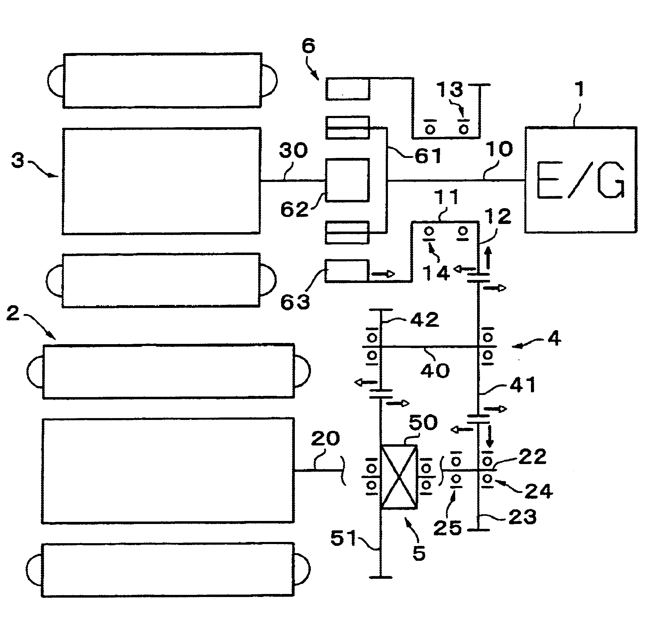
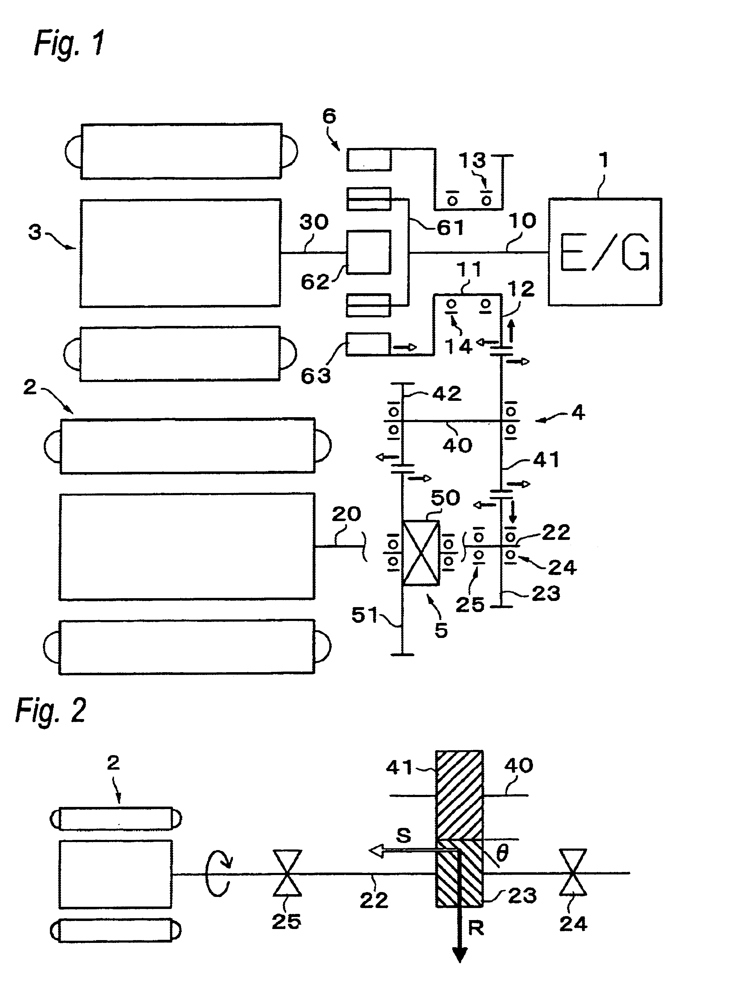
[0044]Hereinafter, embodiments of the invention will be explained with reference to the drawings. First, FIG. 1 is a skeleton diagram showing a developed portion between shafts of a hybrid driving apparatus of the first embodiment to which the invention is applied. The driving apparatus mainly comprises an engine 1, an electric motor (motor, hereinafter) 2, a power generator (generator, hereinafter) 3 and a differential device 5. A planetary gear set 6 having a single pinion constituting a differential gear apparatus and a counter gear mechanism 4 are interposed between the above elements.

[0045]In this driving apparatus, the engine 1, the generator 3 and the planetary gear set 6 are disposed on output shaft axes that extend parallel to each other, the motor 2 is disposed on a motor axis, the counter gear mechanism 4 is disposed on a counter axis, and the differential device 5 is disposed on a differential device axis. These axes are in parallel to each other. The engine 1 and the ge...

fourth embodiment

[0059]FIG. 8 is a skeleton diagram of a hybrid driving apparatus according to the invention in which counter gear mechanisms 4A, 4B are separately provided on the side of the output shaft 11 and on the side of the motor shaft 22. In this embodiment, a first counter driven gear 41 B is disposed at a position close to the motor 2 in a counter shaft 40B of a first counter gear mechanism 4B, and a first differential drive pinion gear 42B is disposed at a position close to the differential device 5. Further, a second counter driven gear 41A is disposed at a position close to the generator 3 of the counter shaft 40A of a second counter gear mechanism 4A, and a second differential drive pinion gear 42A is disposed at a position closer to the differential device 5. In this layout, the first counter drive gear 23 is disposed on the side of the motor shaft 22, and the second counter drive gear 12 is similarly disposed on the side of the output shaft 11. The remaining structure is entirely the...

fifth embodiment

[0060]FIG. 9 is a skeleton diagram of a hybrid driving apparatus according to the invention in which output of the motor is transmitted to the differential device 5 through the output shaft 11. In this embodiment, the first counter gear mechanism 4B is disposed between the motor shaft 22 and the output shaft 11, and a second counter gear mechanism 4A is disposed between the output shaft 11 and the differential shaft. The first counter driven gear 41 B is disposed at a position farther from the motor 2 on the first counter shaft 40B, and a pinion gear 43B which meshes with the second counter drive gear 12 to drive the drive gear 12 as a driven gear is disposed at a position close to the motor 2. In the counter shaft 40A of the second counter gear mechanism 4A, the second counter driven gear 41A is disposed at a position close to the engine, and a differential drive pinion gear 42A is disposed at a position close to the differential device 5. In this layout, the first counter drive ge...


PUM


Abstract

A driving apparatus having a shaft structure that reduces a load on shaft supports and enhances durability of the motor. The driving apparatus includes an electric motor, an electric motor shaft, first and second shaft supports, a counter drive gear on the electric motor shaft, and a counter driven gear to be meshed with the counter drive gear. Output of the electric motor is transmitted to wheels through both of the gears. The counter drive gear is disposed at a position closer to one of the shaft supports, a helix angle is set in a direction in which a thrust force S acts toward the second shaft support, which is farther from the gear. With this arrangement, a load caused by a radial force applied to the first shaft support, which is closer to the counter drive gear, is reduced.

Description

BACKGROUND OF THE INVENTION[0001]1. Field of Invention[0002]The invention relates to a driving apparatus using an electric motor as a power source, and more particularly, to a shaft support structure in a driving apparatus.[0003]2. Description of Related Art[0004]In the case of an electric motor in an electric vehicle driving apparatus using an electric motor as a driving source or in a hybrid driving apparatus and the like (hereinafter generally called a driving apparatus) in which an engine (combustion engine) and an electric motor are used in combination, the motor is required to be smaller in size in view of energy-saving and space-saving. In view of this requirement, for example, Japanese Patent Application Laid-open No. H10-175455 discloses a technique for downsizing an electric motor of a driving apparatus in which a gear ratio of a power transmission system to the wheels is increased using a speed-reduction mechanism such as a counter gear, thereby increasing driving torque ...

Claims


Application Information

Patent Timeline
Patent Type & Authority Patents(United States)
IPC IPC(8): B60K6/04B60K6/00H02K7/10H02K57/00B60K1/02B60K1/00B60K17/22B60K17/24F16H57/02F16H1/20F16H3/72F16H1/02F16H3/44H02K51/00H02K16/00B60K17/04B60K6/20B60K6/36B60K6/365B60K6/445B60K6/448B60L15/20B60L50/16F16H1/08H02K7/116
CPCB60K6/365B60K6/40B60K6/445H02K7/10H02K51/00B60L11/123B60L11/14B60L15/20B60L15/2009B60K6/36B60K1/02B60L2260/26B60K17/24F16H1/20F16H3/727F16H57/021F16H2037/0866H02K16/00Y02T10/7258Y10S903/903Y10S903/951Y10S903/909Y10S903/91Y02T10/6239B60L2240/12B60L2240/421B60L2240/423B60L50/16B60L50/61Y02T10/62Y02T10/64Y02T10/70Y02T10/7072Y02T10/72
Inventor TAKENAKA, MASAYUKI
Owner AISIN AW CO LTD
Why Eureka
Try Eureka