

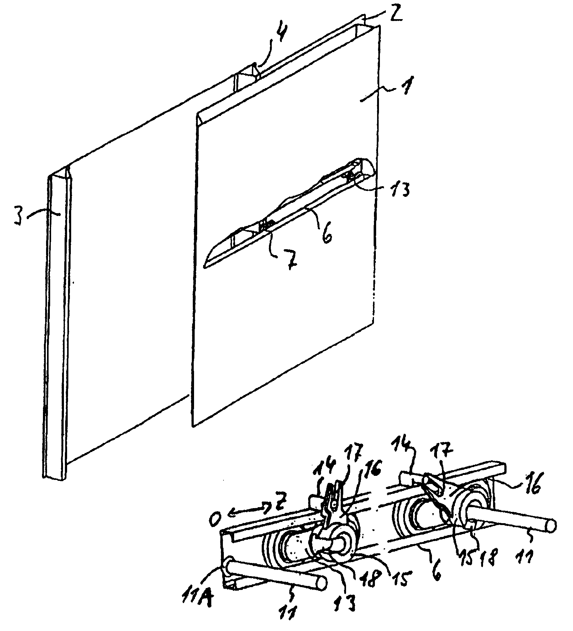
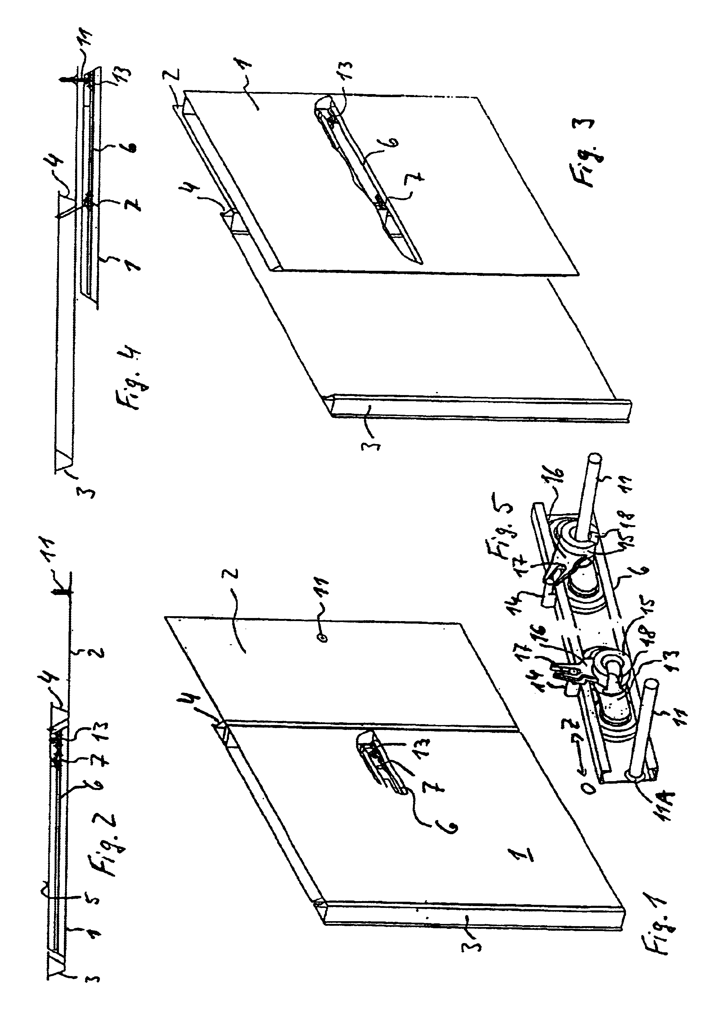
Sliding door guide carriages and running rails on motor vehicles
a technology for sliding doors and motor vehicles, applied in the direction of door/window fittings, vehicle bodies, monocoque constructions, etc., can solve the problems of affecting the design and appearance of the vehicle, and using a particularly expensive material
- Summary
- Abstract
- Description
- Claims
- Application Information
AI Technical Summary
Benefits of technology
Problems solved by technology
Method used
Image

Examples
second embodiment
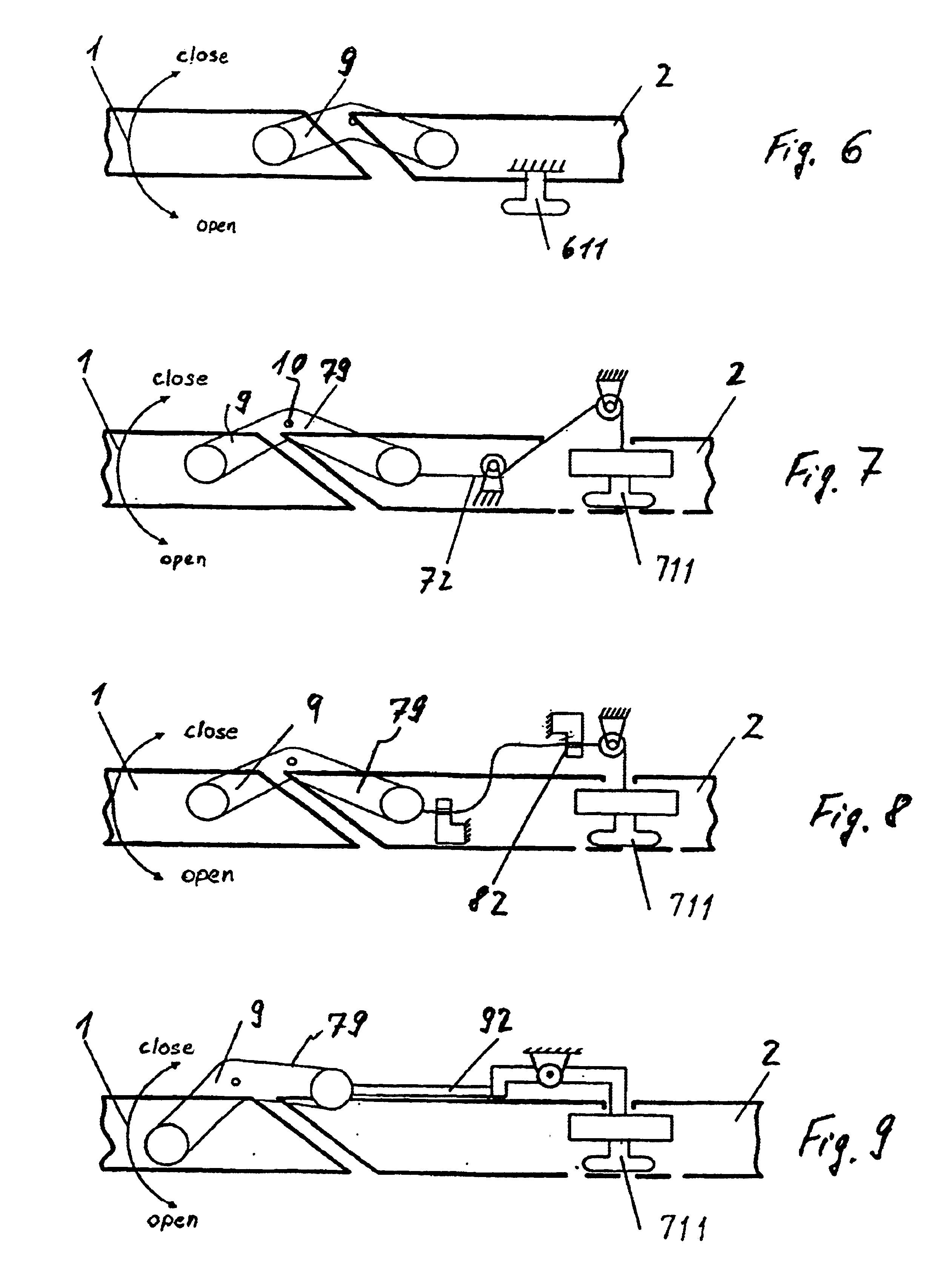
[0050]FIG. 6 contains a top view of a schematic representation of the invention. In this very easy to realise configuration, a fixed bracket 611 is provided as a second anchor in or on side panel 2. The end of this bracket 611 is fixed and permanently projects from side panel 2 and either takes the form of a roller or a roller can even be mounted in that position. Provision is also made in this embodiment for the first anchor that serves sliding rails 6, which are mounted on the inside of door 1, and are not shown in FIG. 6, which runs onto these at projecting bracket 611, which then forms the next fixing point for the encompassing door-guide mechanism 1. When the door opens, reversing lever 9 rotates anticlockwise about axis 10 and carriage 7 linked to this also rotates with sliding rails 6 and door 1 so that door 1 is positioned outside and approximately parallel to side panel 2, as indicated in FIG. 2. During the further opening movement, sliding rails 6 run onto bracket 611.
third embodiment
[0051]According to the invention, a similar roller 711 or a carriage comprising several rollers can be used instead of the free-running roller assembly 13 or a corresponding dead roller in sliding rails 6 on the inside 5 of door 1, as shown in the schematic representation in FIG. 7. Roller 711 acts as the second anchor in this embodiment. Roller 711 or a carriage comprising several rollers as depicted in FIG. 7 can either be permanently mounted on side panel 2 or can be configured so that it can swing out of side panel 2, as depicted in FIG. 7. It is also possible to swivel-mount this roller 711 so that it can swing out of side panel 2 about a vertical or horizontal axis. In this embodiment, sliding rails 6 mounted on the inside of the door serve as the first anchor, and run onto roller 711 when the door opens, which roller has either swung outwards or permanently projects outwards. In this way, sliding rails 6 lock encompass roller 711 in this position and together they form the ne...
PUM
 Abstract
Description
Claims
Application Information