Turbine engine sealing device

a sealing device and turbine engine technology, applied in the field of turbine engines, can solve the problems of inability to reduce the gap and the gap is minimal, and achieve the effects of reducing the size of the gap, reducing the leakage of air, and increasing the efficiency of the turbine engin

Inactive Publication Date: 2005-05-24
SIEMENS ENERGY INC
View PDF16 Cites 24 Cited by
  • Summary
  • Abstract
  • Description
  • Claims
  • Application Information

AI Technical Summary

Benefits of technology

[0005]This invention relates to a sealing system for reducing a gap between a tip of a turbine blade and a shroud of a turbine engine. As a turbine engine reaches steady state operation, components of the sealing system reach their maximum expansion and reduce the size of the gap located between the blade tips and the engine shroud, thereby reducing the leakage of air past the turbine blades and increasing the efficiency of the turbine engine. In at least one embodiment, the sealing system includes a turbine blade assembly having at least one stage formed from a plurality of turbine blades. The sealing system also includes a blade ring radially surrounding the turbine blade assembly such that the blade ring may radially expand and contract during operation as a result of thermal expansion or contraction. A ring segment having at least one surface positioned in close proximity to at least one tip of the turbine blade assembly may be positioned such that the ring segment forms a gap between the at least one surface of the ring segment and the plurality of blades. A spindle may be fixed to the blade ring at a first end of the spindle and coupled to the ring segment at a second end of the spindle for supporting and positioning the ring segment in close proximity with at least one tip of the plurality of blades. The spindle may be formed from a material having a coefficient of thermal expansion that is greater than a coefficient of thermal expansion for a material forming the ring segment.
[0006]While the turbine engine is at rest, there exists a gap between the blade tips and the ring segments. During operation, the ring segments reach maximum operating temperature before the turbine blade assembly. As the ring segments are heated, the spindle lengthens a greater amount than the blade ring. In other words, the length of the spindle increases a greater distance than the diameter of the blade ring increases. As a result, the ring segment attached to the end of the spindle undergoes a net radial displacement towards the tips of the blades. As the turbine blade assembly reaches its maximum operating temperature, the blades lengthen to their steady state operating positions. Operating a turbine engine using this sealing system reduces the gap between the tips of the turbine blades and the ring segments by about 0.04 inches to about 0.05 inches, depending on the difference in thermal expansion coefficients between the spindle and the blade ring. The larger the difference in coefficients of the spindle and the blade ring, the larger the reduction in gap spacing. Upon shutdown, even in emergency conditions, the ring segment undergoes a net radial displacement away from the blade tips, thereby preventing the blade tips from contacting the ring segments.
[0007]An advantage of this invention is that the size of the gap between blade tips and shrouds of turbine engines may be reduced without introducing the possibility that the blade tips may contact the shroud, thereby damaging the turbine engine.

Problems solved by technology

However, reducing the gap cannot be accomplished by simply positioning the components so that the gap is minimal under full load conditions because the configuration of the components forming the gap must account for emergency shutdown conditions in which the shroud, having less mass than the turbine blade and disc assembly, cools faster than the turbine blade assembly.
Collision of the turbine blades and the shroud often causes catastrophic results.

Method used


Image

  • Turbine engine sealing device
  • Turbine engine sealing device
  • Turbine engine sealing device

Examples


Embodiment Construction

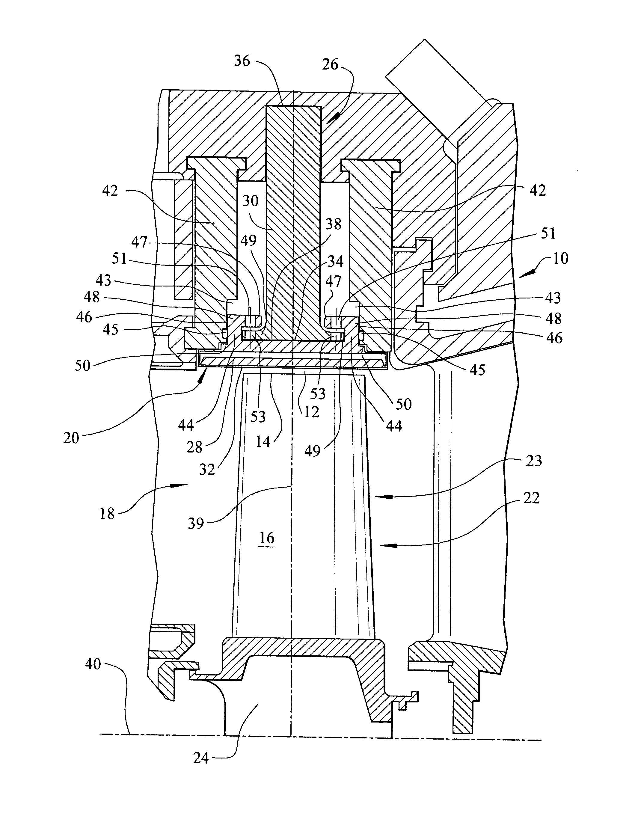
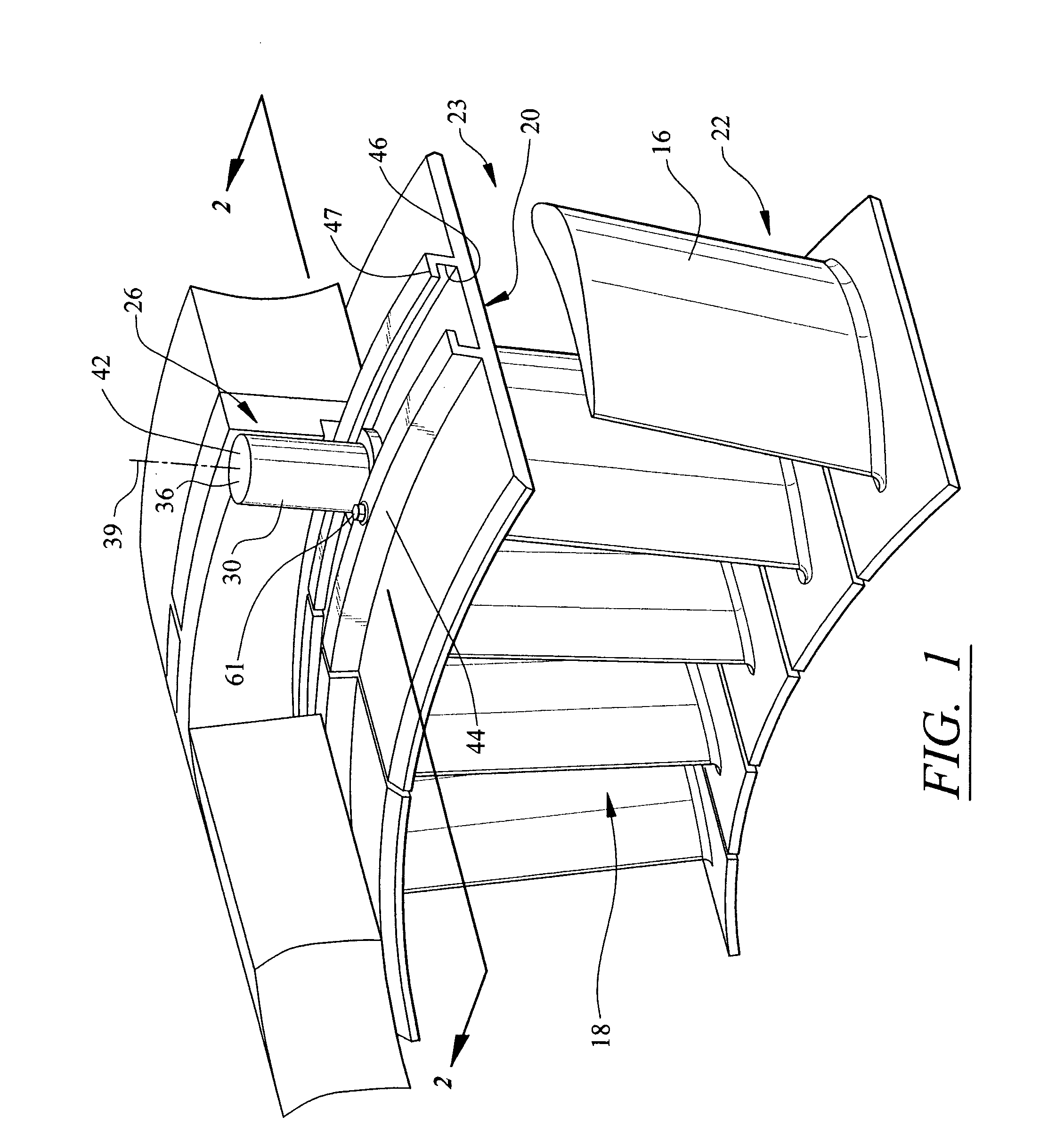
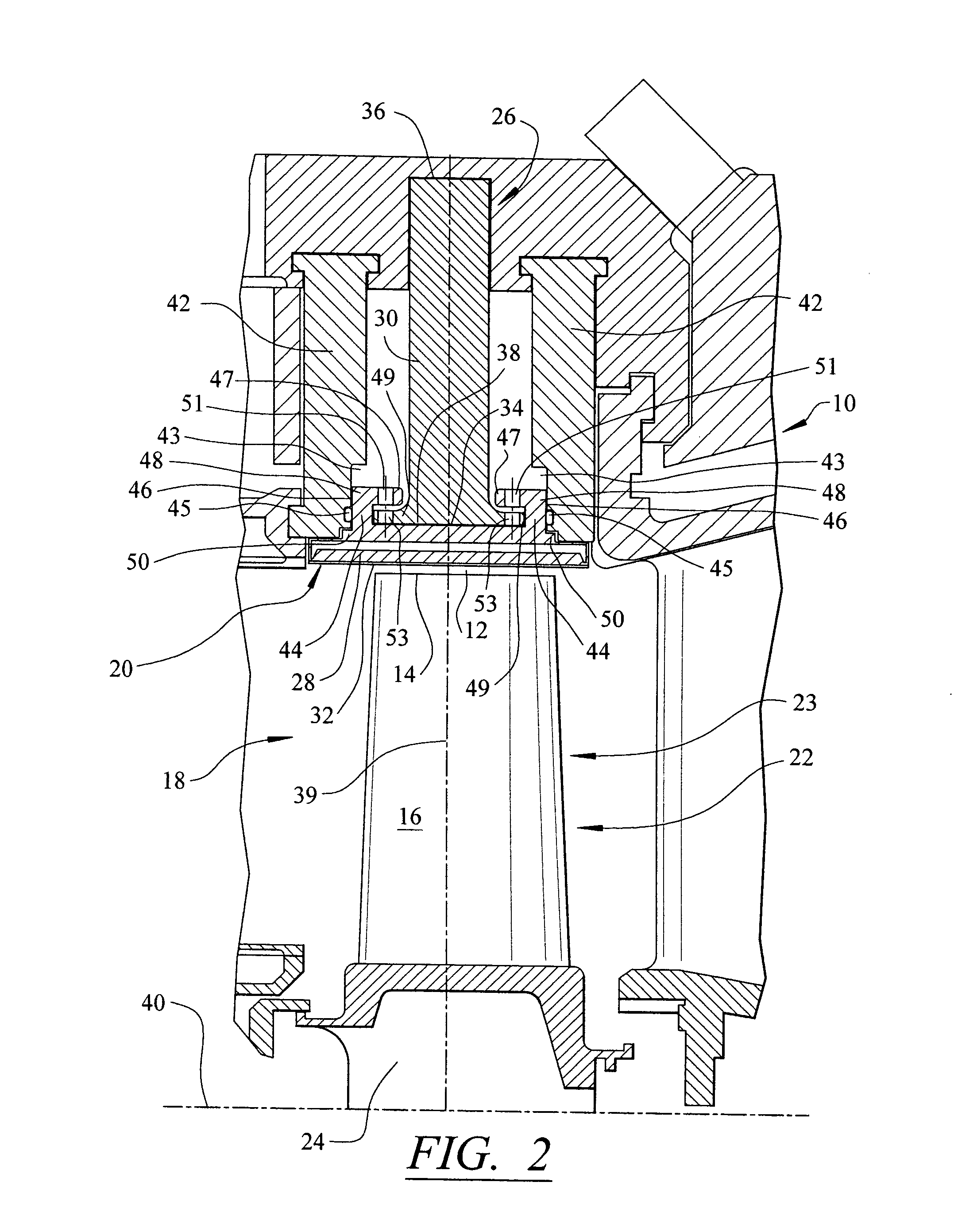
[0012]As shown in FIGS. 1–2, this invention is directed to a sealing system 10 for a turbine engine. In particular, the sealing system 10 is operable to reduce a gap 12 between one or more tips 14 of a turbine blade 16 in a turbine engine 18 and a surrounding shroud 20 while the turbine engine 18 is operating. The gap 12 exists in the turbine engine 18 so that the tips 14 do not contact the shroud 20. In at least one embodiment, the turbine engine 18 includes a turbine blade assembly 22 formed at least in part from a plurality of turbine blades 16 coupled to a disc 24. The blades 16 may be coupled to the disc 24 at various points along the disc 24 and may be assembled into rows, which are commonly referred to as stages 23, having adequate spacing to accommodate stationary vanes between adjacent stages of the blades 16. The stationary vanes are typically mounted to a casing of the turbine engine 18. The disc 24 may be rotatably coupled to the turbine engine 18.

[0013]The turbine engi...


PUM


Abstract

A sealing system for reducing a gap between a tip of a turbine blade and a shroud of a turbine engine. As a turbine engine reaches steady state operating conditions, components of the sealing system reach their maximum expansion and reduce the size of the gap located between the blade tips and the engine shroud, thereby reducing the leakage of air past the turbine blades and increasing the efficiency of the turbine engine. The sealing system includes a ring segment having a sealing surface positioned proximate to a tip of a turbine blade. The ring segment may be coupled to a blade ring using a spindle having a coefficient of thermal expansion greater than the coefficient of thermal expansion for the blade ring.

Description

FIELD OF THE INVENTION[0001]This invention is directed generally to turbine engines, and more particularly to systems for sealing gaps between blade tips and shrouds in turbine engines.BACKGROUND[0002]Typically, gas turbine engines are formed from a combustor positioned upstream from a turbine blade assembly. The turbine blade assembly is formed from a plurality of turbine blade stages coupled to discs that are capable of rotating about a longitudinal axis. Each turbine blade stage is formed from a plurality of blades extending radially about the circumference of the disc. Each stage is spaced apart from each other a sufficient distance to allow turbine vanes to be positioned between each stage. The turbine vanes are typically coupled to the shroud and remain stationary during operation of the turbine engine.[0003]The tips of the turbine blades are located in close proximity to an inner surface of the shroud of the turbine engine. There typically exists a gap between the blade tips ...

Claims


Application Information

Patent Timeline
Patent Type & Authority Patents(United States)
IPC IPC(8): F01D11/08F01D11/18
CPCF01D11/18
Inventor DIAKUNCHAK, IHOR S.
Owner SIEMENS ENERGY INC
Why Eureka
Try Eureka