
Elastic roller and process for producing same

a technology of elastic rollers and rollers, applied in the field of rollers, can solve the problems of high axial stress between steel or chilled iron rollers and plastic coatings, destroying plastic layers, and aforementioned destruction of plastic layers, and achieve the effect of reducing the risk of hot spots

Inactive Publication Date: 2005-05-24
VOITH PATENT GMBH
View PDF34 Cites 16 Cited by
  • Summary
  • Abstract
  • Description
  • Claims
  • Application Information

AI Technical Summary

Benefits of technology

[0010]The present invention provides a process for producing an elastic roller of the type generally discussed above, as well as a corresponding roller, in which the risk of the occurrence of hot spots is reduced.
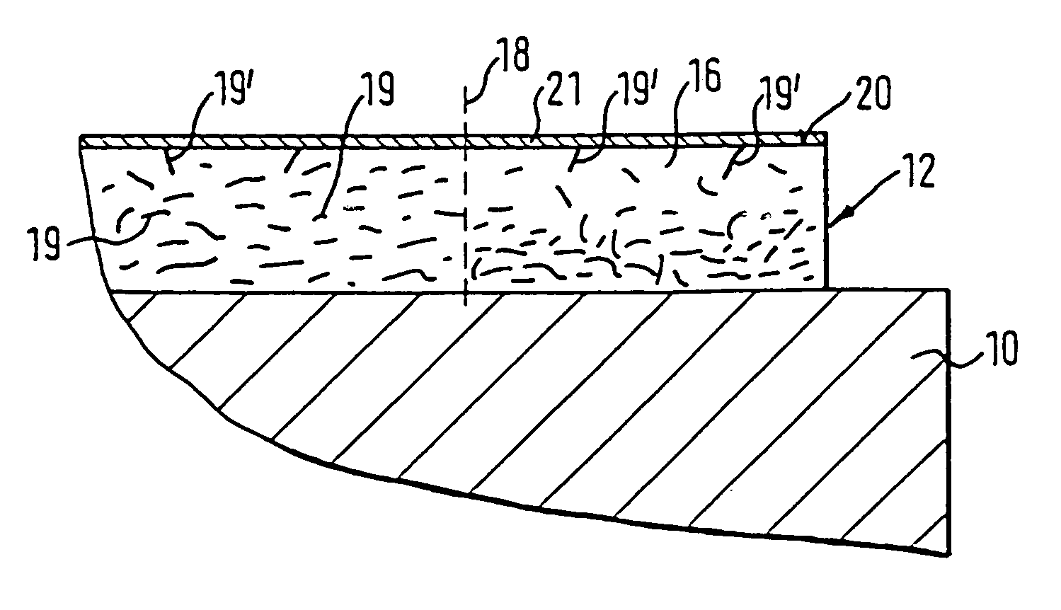
[0012]The metallic fillers introduced into the matrix material result in an improved thermal conductivity of the elastic coating layer and a reduced dissipation in comparison to, e.g., aramide or glass fibers used as fillers. Due to the increased thermal conductivity the superheat occurring at critical locations can be dissipated more quickly so that a surpassing of the critical temperature and, thus, the occurrence of hot spots can be prevented. In this context, because of the high thermal conductivity of a metallic filler an especially quick dissipation of excess heat, for example, in the direction to the roller core is possible.
[0014]Moreover, since the thermal expansion coefficient of the metallic fillers is smaller than the thermal expansion coefficient of the matrix material, it is achieved that the total thermal expansion coefficient of the coating layer is also smaller than that of the matrix material. In particular, by selecting a suitable metal for the fillers the total thermal expansion coefficient of the coating layer can be adjusted to the thermal expansion coefficient of the roller core. In this way, the longitudinal stresses between the coating layer and the roller core occurring upon heating of the roller can be reduced and, in an optimal situation, can be completely compensated. With this reduction or prevention of the longitudinal stresses, the risk of the occurrence of hot spots, respectively, of the detachment of the cover layer can be further reduced simultaneously.
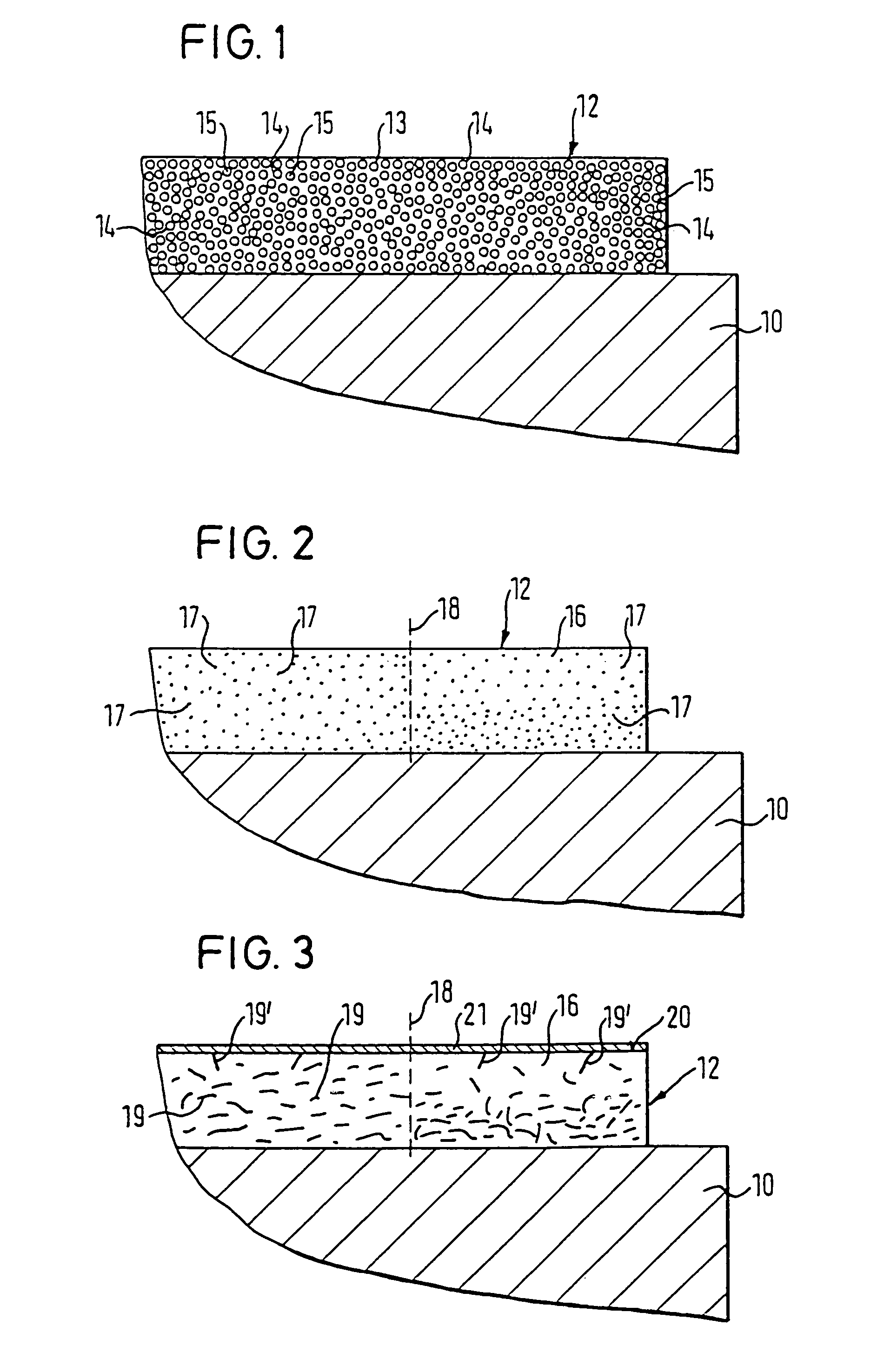
[0019]In an embodiment as a metal foam, as well as in an embodiment as a metal powder, a very uniform distribution of the metallic fillers over the entire volume of the matrix material and, thus, of the elastic coating layer is possible. In particular, a uniform distribution in the radial direction ensures that the heat occurring at a hot spot within the elastic coating layer can be dissipated in the direction toward the roller core and can be subsequently dissipated by it, e.g., in the axial direction. In this context it is advantageous when the metallic fillers extend radially without substantial disruptions down to the surface of the roller core.
[0023]While in the use of metal powder or fibers the elasticity of the matrix material is still of great importance for the total elasticity of the coating layer, in the case employing a metal foam the elasticity of the coating layer is more strongly determined by the metal foam. It is therefore advantageous to employ an elastic metal foam so that the coating layer overall still has the required elasticity.
[0026]For producing a smooth surface of the roller, the coating layer is advantageously ground after application and drying. This may result in the metallic fillers embedded in the coating layer, when they extend into close proximity to the surface of the coating layer, to become exposed by the grinding process. This is especially advantageous when the surface of the matrix material is additionally coated with a metal for producing an extremely smooth surface because the metallic fillers exposed at the surface of the elastic matrix material provide very good anchoring points for the externally positioned metal coating.

Problems solved by technology

These high temperatures resulting from online operation lead to problems which, in the known elastic rollers, can ultimately lead to the destruction of the plastic coating.
Therefore, a temperature increase causes high axial stress between the steel or chilled iron roller and the plastic coating connected thereto.
In these cases the temperature at these crystallization points of conventionally 80° C. to 90° C. can increase to 150° C. resulting in the aforementioned destruction of the plastic layer.

Method used


Image

  • Elastic roller and process for producing same
  • Elastic roller and process for producing same
  • Elastic roller and process for producing same

Examples


Embodiment Construction

[0060]The particulars shown herein are by way of example and for purposes of illustrative discussion of the embodiments of the present invention only and are presented in the cause of providing what is believed to be the most useful and readily understood description of the principles and conceptual aspects of the present invention. In this regard, no attempt is made to show structural details of the present invention in more detail than is necessary for the fundamental understanding of the present invention, the description taken with the drawings making apparent to those skilled in the art how the several forms of the present invention may be embodied in practice.

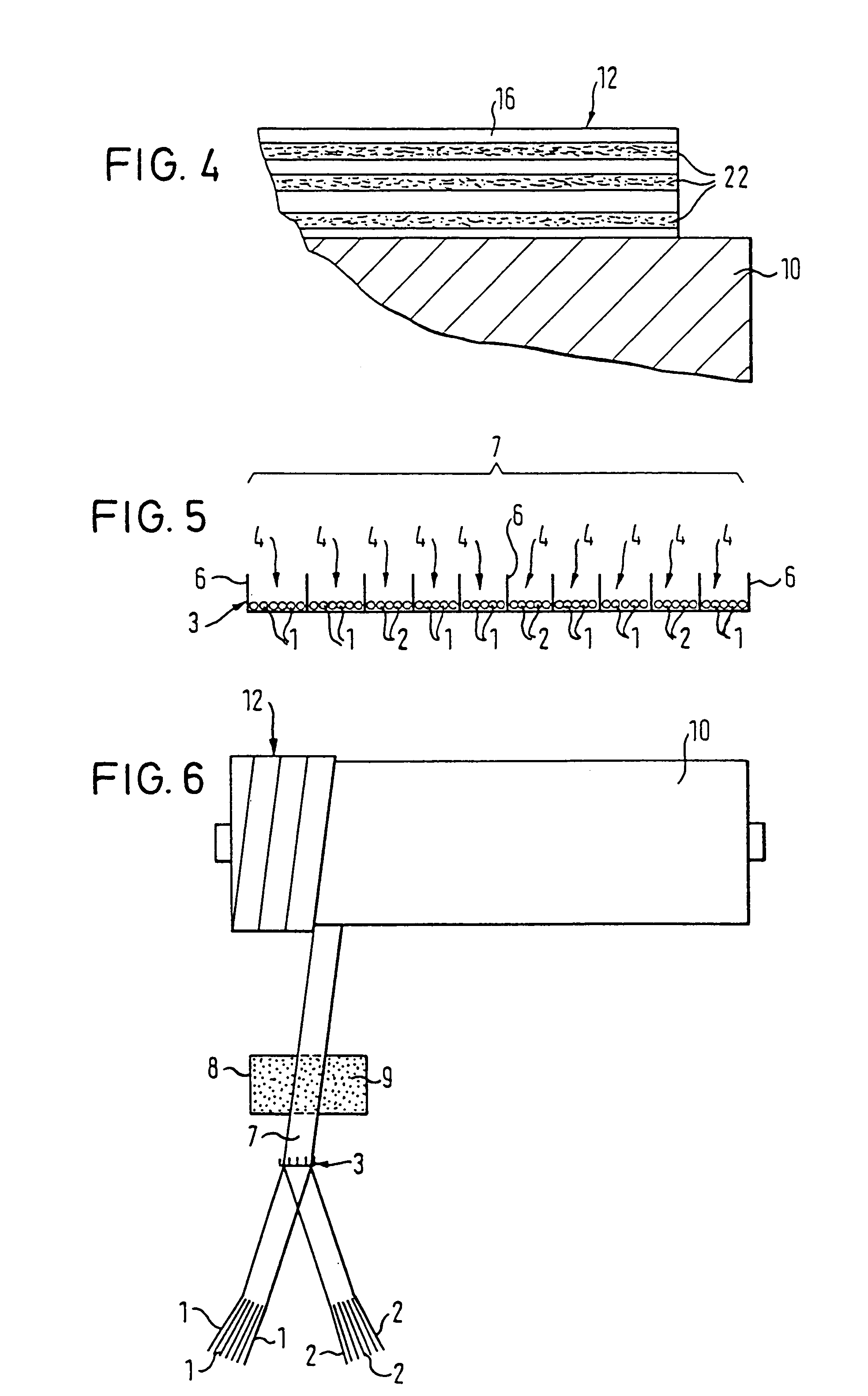
[0061]FIG. 1 illustrates a portion of a roller core 10 in longitudinal section, comprised of, e.g., steel or chilled iron. At an outer side of roller core 10, an elastic coating layer 12 is provided.

[0062]Coating layer 12 can include, e.g., an elastic metal foam 13 having a plurality of pores 14. Pores 14 are filled with ...


PUM

PropertyMeasurementUnit
Pressureaaaaaaaaaa
Lengthaaaaaaaaaa
Lengthaaaaaaaaaa

Abstract

Elastic roller and process for producing elastic roller. The elastic roller includes a hard roller core and an elastic coating layer at an outer side of the hard roller core. The elastic coating layer includes an elastic matrix material and fillers imbedded in the matrix material, and at least a portion of the fillers include metallic fillers. The process includes combining at least one metallic filler into an elastic matrix material and applying the combined elastic matrix material and at least one metallic filler onto an outer side of the hard roller core to form an elastic coating layer.

Description

CROSS-REFERENCE TO RELATED APPLICATIONS[0001]The present application claims priority under 35 U.S.C. § 119 of German Patent Application No. German Patent Application No. 199 25 421.4, filed on Jun. 2, 1999, the disclosure of which is expressly incorporated by reference herein in its entirety.BACKGROUND OF THE INVENTION[0002]1. Field of the Invention[0003]The present invention relates to a roller, e.g., for smoothing paper webs. The roller includes a hard roller core, which includes metal, and an elastic coating layer located on an outer side of the hard roller core. The elastic coating layer includes an elastic matrix material and fillers embedded in the matrix material. Furthermore, the invention relates to a process for producing such a roller.[0004]2. Discussion of Background Information[0005]Elastic rollers of this kind are, for example, used in glazing of paper webs. In this context, an elastic roller and a hard roller, respectively, together form a pressing nip through which t...

Claims


Application Information

Patent Timeline
IPC IPC(8): D21G1/00D21G1/02F16C13/00
CPCD21G1/0233F16C13/00Y10T29/49549
Inventor KARGER, JENS CHRISTIANVODERMAYER, ALBERT MARIA
Owner VOITH PATENT GMBH
Learn More