Microplate cover assembly

a microplate and assembly technology, applied in the field of microplates, can solve the problems of non-uniform distribution, many conventional seals do not provide a uniform seal across all of the wells of the microplate, and the conventional seals suffer from significant disadvantages

Inactive Publication Date: 2005-05-24
TEKCEL
View PDF93 Cites 47 Cited by
  • Summary
  • Abstract
  • Description
  • Claims
  • Application Information

AI Technical Summary

Benefits of technology

[0007]In a preferred embodiment, the cover includes a number of laterally-extending tabs which serve as gripping points for a robotic microplate handling system. Such tabs enable a robotic manipulator to engage the cover with a microplate, disengage the cover, and transport the engaged cover / microplate as a unit. The cover may also include a number of downwardly-extending tabs which enable multiple units to be stacked in a stable manner. The embodiment is designed to not obstruct the surfaces of the microplate where barcodes are typically applied. The pressure plate may include features for holding the assembly for robotic handling.

Problems solved by technology

In addition, some test procedures, including high throughput screening, may require a large number (e.g., on the order of hundreds or thousands) of microplates to be handled by robotic equipment.
Conventional approaches to sealing microplates suffer from significant disadvantages.
First, many conventional seals do not provide a uniform seal across all of the microplate's wells.
This is often caused by a non-uniform distribution of force which is used to maintain the seal.
In more serious cases, this flaw may result in incomplete sealing of some wells, thereby compromising test results or creating a hazardous condition.
Second, conventional seals are typically designed to be engaged and disengaged from the microplate by hand and are not suitable for use with robotic equipment needed for high throughput screening.

Method used


Image

  • Microplate cover assembly
  • Microplate cover assembly
  • Microplate cover assembly

Examples


Embodiment Construction

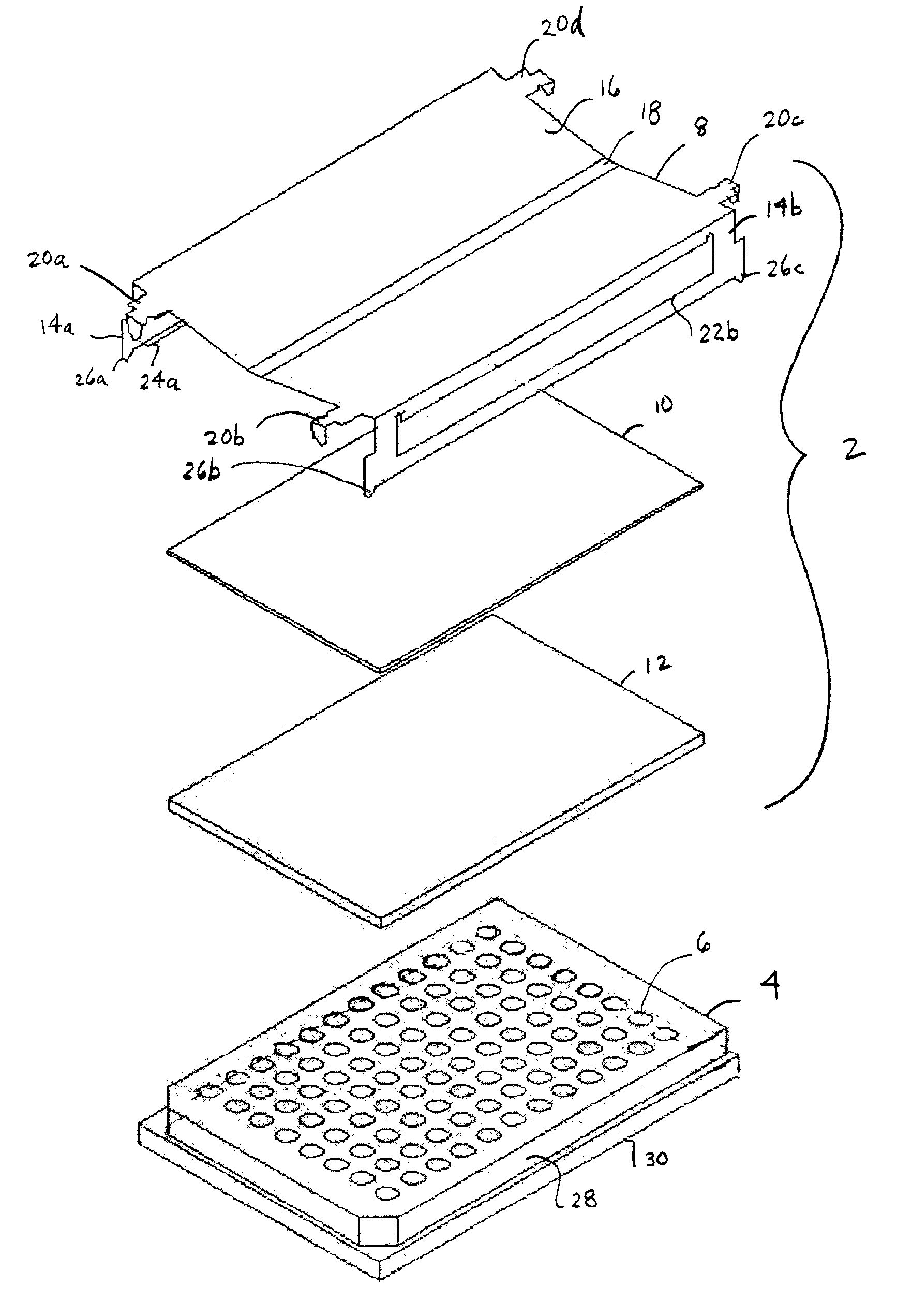
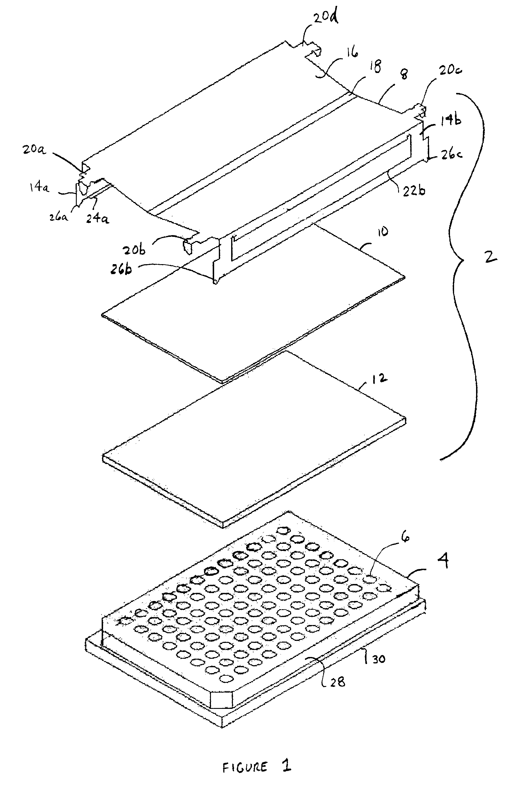
[0018]EMBODIMENT FIG. 1 shows a microplate cover assembly 2 which may be used to seal wells 6 contained in a microplate 4. Microplate 4 is of conventional design and is available from any of a number of commercial sources in any of 24, 96 or 384 well formats, and may include others. It should be understood that the term “microplate” as used herein includes, but is not limited to, shallow well, deepwell, half deepwell and PCR type plates as well as minitube racks. It should also be understood that the present invention is not limited to any particular matrix size.

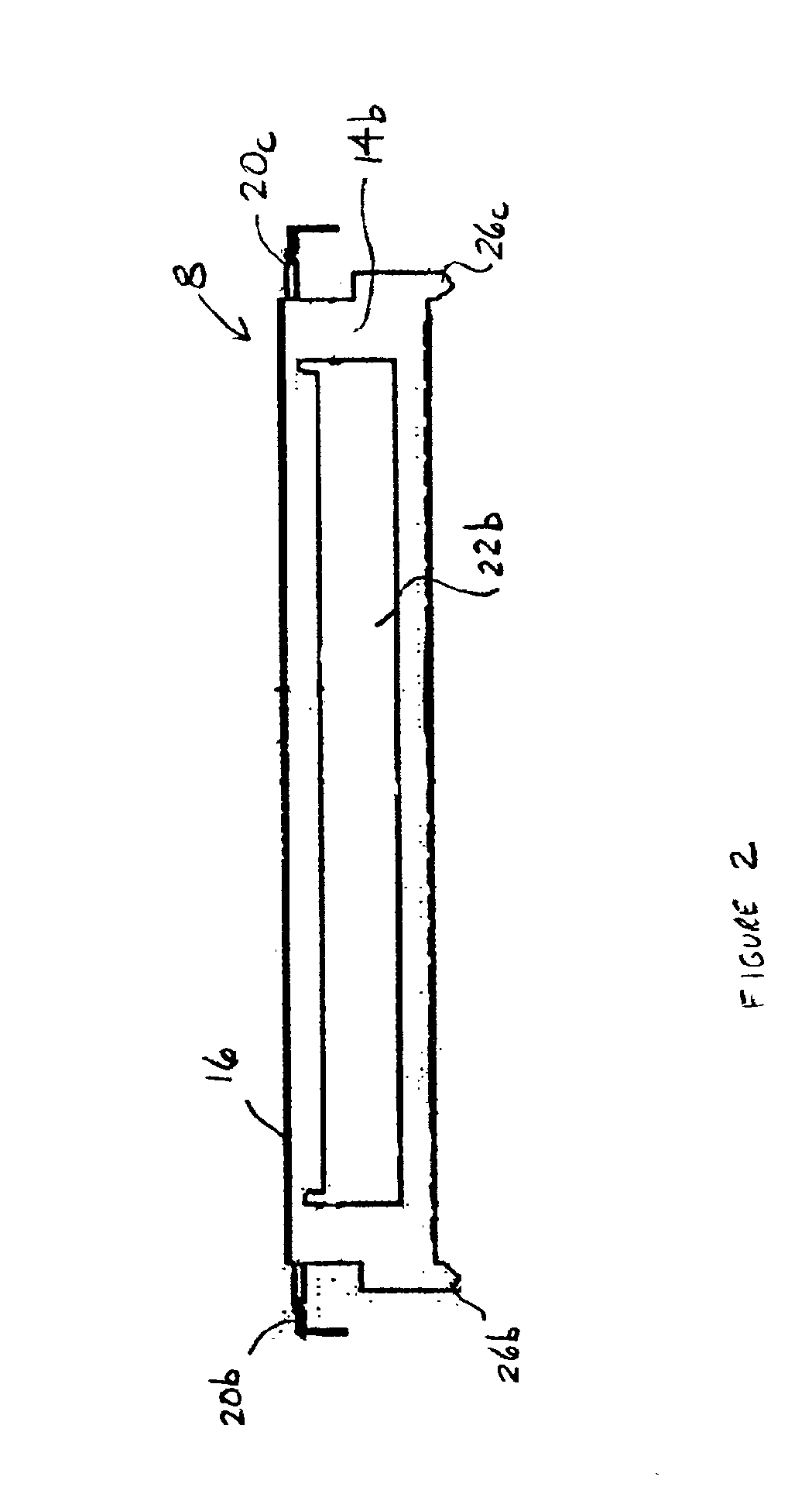
[0019]A cover 8 is disposed on a pressure plate 10. Pressure plate 10 is disposed on a layer of sealing material 12, which in turn is disposed on the top surface of microplate 4. Cover 8 includes an angled top surface 16 with a narrow, generally flat portion 18 extending laterally along the central axis of the cover. Cover 8 includes sides 14a and 14b which are generally orthogonal to top surface 16. Extending laterally from...


PUM

PropertyMeasurementUnit
compressive forceaaaaaaaaaa
pressureaaaaaaaaaa
resilient forceaaaaaaaaaa

Abstract

A microplate cover assembly which is compatible with manual workstations or robotic handling systems used for high throughput screening. The cover assembly includes a cover, a pressure plate and a layer of sealing material. The cover is shaped such that when it is engaged with a microplate, the cover exerts a compressive force on the pressure plate, which in turn disperses the force in a substantially uniform manner across the layer of sealing material. The cover and pressure plate also include laterally-extending tabs which allow it to be engaged with or disengaged from a microplate in a fully automated fashion.

Description

BACKGROUND OF THE INVENTION[0001]1. Field of the Invention[0002]The present invention relates generally to the field of microplates and, more specifically, to a microplate cover assembly which provides a removable seal and is compatible with manual or robotic handling systems.[0003]2. Background Information[0004]Microplates are commonly used in a variety of test procedures. During such procedures, it may be desirable or necessary to seal the wells contained in the microplates in order to produce appropriate test conditions, prevent cross-contamination among wells, prevent sample leakage during transportation or storage, or prevent human exposure to hazardous samples. In addition, some test procedures, including high throughput screening, may require a large number (e.g., on the order of hundreds or thousands) of microplates to be handled by robotic equipment. In such an environment, it is essential is that the process of engaging or disengaging the microplate's seal does not interfe...

Claims


Application Information

Patent Timeline
Patent Type & Authority Patents(United States)
IPC IPC(8): B01L3/00G01N35/02B65D45/02B65D77/20B81B1/00C40B60/14G01N37/00
CPCB01L3/50853B01J2219/00317B01J2219/00587C40B60/14B01J2219/00691
Inventor WARHURST, JULIAN D.ZAAYENGA, ANDREW F.
Owner TEKCEL
Why Eureka
Try Eureka