Stabilized power supply unit having a current limiting function

a power supply unit and function technology, applied in the direction of power supply lines, instruments, vehicle components, etc., can solve the problems of affecting the smooth rise of output voltage vo, loss of series regulator control, and automatic limitation of output current io, so as to prevent oscillation and minimize the overcurrent region

Inactive Publication Date: 2005-05-24
ROHM CO LTD
View PDF5 Cites 36 Cited by
  • Summary
  • Abstract
  • Description
  • Claims
  • Application Information

AI Technical Summary

Benefits of technology

[0016]It is, therefore, an object of the invention to provide a stabilized power supply unit having a current limiting function that is capable of: furnishing a steep drop-type over-current protec...

Problems solved by technology

However, if the output current exceeds a predetermined level (over-current protection level Is0), the output current Io is automatically limited.
Then, if the over-current region a is too small, inrush current to the condenser Co will cause an oscillation at the time of startup.
In this manner, the control of the series regulator is lost, creating an oscillation in the circuit, which hinders a smooth rise of output volta...

Method used


Image

  • Stabilized power supply unit having a current limiting function
  • Stabilized power supply unit having a current limiting function
  • Stabilized power supply unit having a current limiting function

Examples


Embodiment Construction

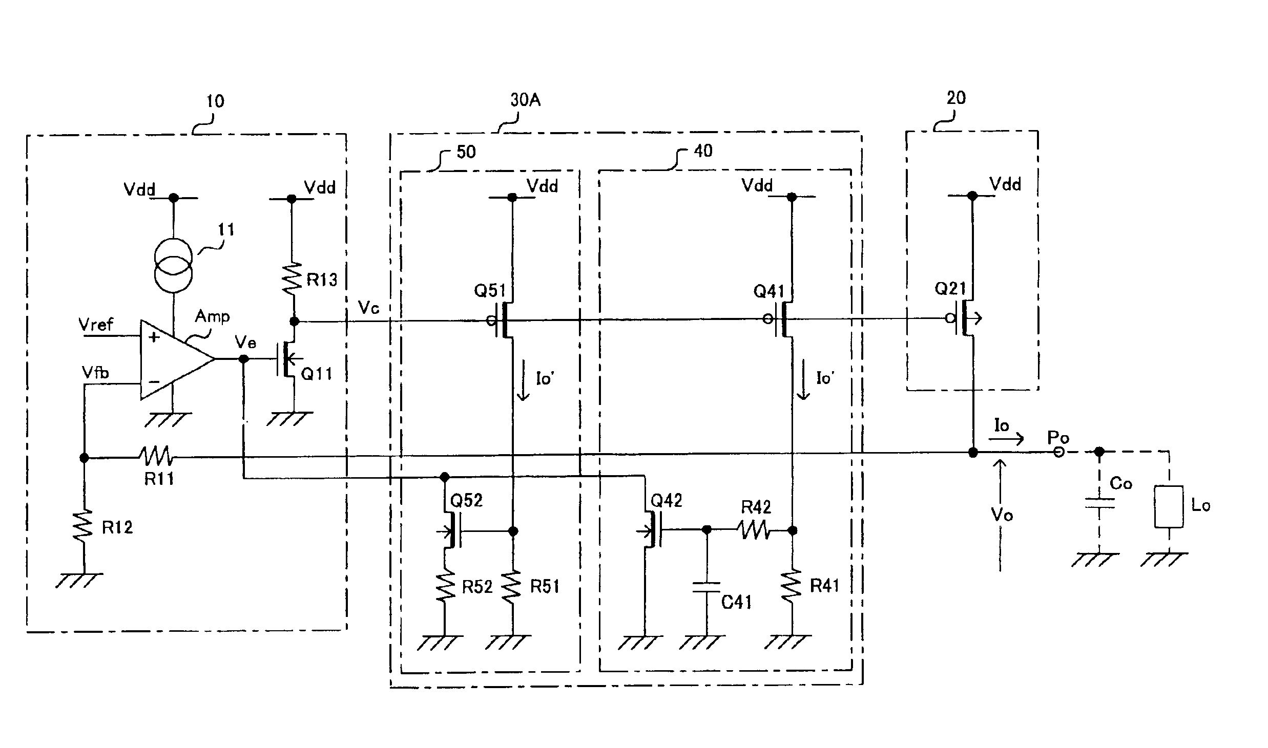
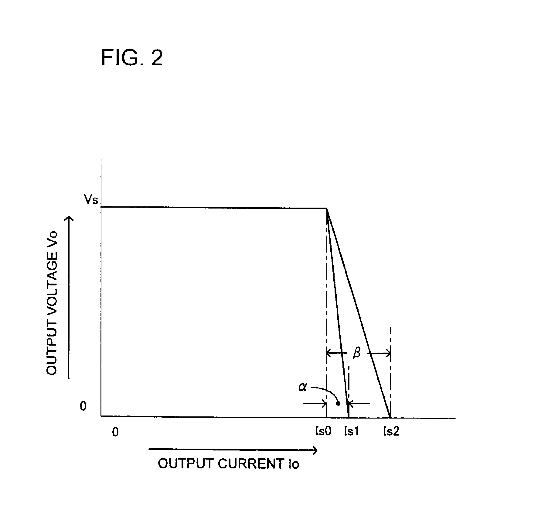
[0045]The invention will now be described in detail by way of examples with reference to accompanying drawings. FIG. 1 shows a circuit arrangement of a series regulator in accordance with a first embodiment of the invention. FIG. 2 shows the output voltage Vo versus output current Io characteristic of the series regulator. FIG. 3 shows a time rate of change in output voltage Vo as a function of output current Io during a startup of the series regulator.

[0046]Series regulator shown in FIG. 1 is composed of a voltage control circuit 10, an output circuit 20, and a current limiting circuit 30A, all formed on an IC chip.

[0047]The voltage control circuit 10 is provided with a differential amplifier Amp and voltage dividing resistors R11 and R12. One input (non-inverting input) of the differential amplifier Amp is supplied with a reference voltage Vref for setting up an output voltage, while the other input (inverting input) is supplied with an output feedback voltage Vfb generated by div...


PUM


Abstract

In a stabilized power supply unit having a current limiting function, the unit is designed to have a steep over-current dropping characteristic. This minimizes the over-current region, prevents oscillation during a startup, and limits inrush current during a start up within a predetermined range. The output voltage of the power supply unit provides a constant output voltage by controlling an output transistor by means of a differential amplifier amplifying the difference between a reference voltage and an output feedback voltage. The power supply unit has a first high-gain, slow-response type current limiting circuit that outputs a first current limiting signal when the output current of the power supply unit exceeds a predetermined level, and a second low-gain, quick-response type current limiting circuit that outputs a second current limiting signal when the outputs exceeds the predetermined level.

Description

FIELD OF THE INVENTION[0001]The invention relates to a stabilized power supply unit having a current limiting function for maintaining at a constant level the output voltage supplied to a load if the output current to the load has changed, and restricting excessive output current to the load.BACKGROUND OF THE INVENTION[0002]A stabilized power supply unit having a current limiting function is widely used in a series regulator serving as a convenient power supply unit and a constant voltage charging apparatus for charging a battery.[0003]FIG. 5 shows a circuit structure of a series regulator having a conventional current limiting function.[0004]The series regulator shown in FIG. 5 is composed of a voltage control circuit 10, an output circuit 20, and a current limiting circuit 30, integrated on an IC chip.[0005]The voltage control circuit 10 is provided with a differential amplifier Amp and voltage dividing resistors R11 and R12. The differential amplifier Amp is provided at one input...

Claims


Application Information

Patent Timeline
IPC IPC(8): G05F1/10G05F1/573G05F1/56G05F3/26
CPCG05F1/573Y10S323/908
Inventor MIYANAGA, KOICHIISHIKAWA, HIROYUKI
Owner ROHM CO LTD
Why Eureka
Try Eureka