Duty-cycle adjustable buffer and method and method for operating same

a buffer and duty cycle technology, applied in the field of buffers, can solve the problems of increasing the operating speed of the circuit system, affecting the operation efficiency of the whole circuit system, and the complexity of the circuitry of the integrated circui

Active Publication Date: 2005-05-24
VIA TECH INC
View PDF4 Cites 75 Cited by
  • Summary
  • Abstract
  • Description
  • Claims
  • Application Information

AI Technical Summary

Benefits of technology

[0011]The present invention provides a method for adjusting duty cycle of clock signals used in a first and a second inverters connected with each other in series, where each of the first and the second inverters comprises a plurality of current charging paths and a plurality of current discharging paths. When it is requested to reduce the duty cycle of at least one clock signal, the number of current charging paths of the first inverter in the operating states is selectively increased and the number of current discharging paths of the second inverter in the operating states is selectively increased. When it is requested to increase the duty cycle of at least one clock signal, the number of current discharging paths of the first inverter in the operating states is selectively increased and the number of current charging paths of the second inverter in the operating states is selectively increased.

Problems solved by technology

If the quality of a clock signal is not well maintained, the operating speed of the circuit system may not be increased, or even the whole circuit system fails to operate.
With increasing development, the circuitries of integrated circuits become more and more complicated.
However, once the plurality of clock signals are divided side-by-side, the energy of each clock signa

Method used


Image

  • Duty-cycle adjustable buffer and method and method for operating same
  • Duty-cycle adjustable buffer and method and method for operating same
  • Duty-cycle adjustable buffer and method and method for operating same

Examples


Embodiment Construction

[0020]As previously described, the conventional buffer has the problem of lowering quality of clock signals, resulting in a distorted clock signal with a duty cycle greater or less than 50%. Therefore, the present invention provides a duty-cycle adjustable buffer and its operating method to be used in a clock tree circuit. By means of the buffer and the method of the present invention, the duty cycle of the inputted clock signal is identical to that of the clock signal outputted from the clock tree circuit. Furthermore, the voltage level of the clock signal can be appropriately maintained so as to provide sufficient energy to drive the next-stage buffers.

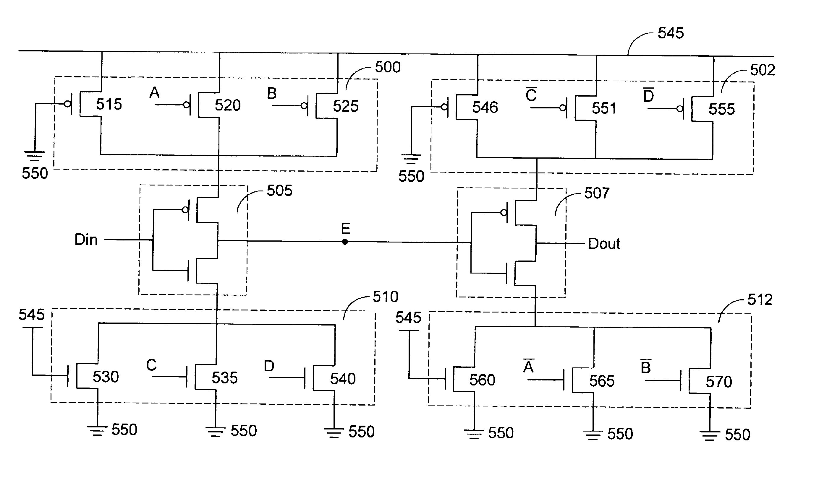
[0021]An embodiment of the present invention will be described in more details with reference to FIG. 5. The duty-cycle adjustable buffer shown in FIG. 5 is implemented by a pair of programmable inverters 505 and 507 connected with each other in series, a first PMOS transistor group 500, a second PMOS transistor group 502, a first N...


PUM


Abstract

A duty-cycle adjustable buffer and a method for operating such buffer can be applied to a clock tree circuit for providing an adjustable duty cycle. The duty-cycle adjustable buffer includes a first inverter and a second inverter connected with each other in series. Each of the first inverter and the second inverter includes a plurality of controlled current charging paths and a plurality of controlled current discharging paths, wherein at least one controlled current charging path and at least one controlled current discharging path of the first inverter and the second inverter are conducted. The timing of the rising edge and falling edge of a clock signal is dynamically adjusted so as to dynamically altering the duty cycle of the clock signal.

Description

FIELD OF THE INVENTION[0001]The present invention relates to a buffer and its operating method, and more particularly to a buffer for use in a clock tree circuit to control a duty cycle of a clock signal and a method for operating such buffer.BACKGROUND OF THE INVENTION[0002]Generally, clock signals with one or more frequencies are required for many recent integrated circuits. The timing and processing speed of an integrated circuit can be realized according to the clock signals to be used. The operating speed of the circuit system is increased as the frequencies of clock signals thereof increase. Thus, the quality of a clock signal is very important for the circuit system. If the quality of a clock signal is not well maintained, the operating speed of the circuit system may not be increased, or even the whole circuit system fails to operate.[0003]When the quality of clock signals of the circuit system is taken into consideration, in addition to their accuracy, more attention should...

Claims


Application Information

Patent Timeline
IPC IPC(8): H03K3/00H03K3/017H03K5/15H03K5/156
CPCH03K5/1565H03K5/1506
Inventor CHANG, CHI
Owner VIA TECH INC
Why Eureka
Try Eureka