Combined antenna with antenna combining circularly polarized wave antenna and vertical antenna

a technology of circular polarization wave antenna and vertical antenna, which is applied in the direction of polarised antenna unit combination, resonant antenna, independent non-interacting antenna combination, etc., can solve the problems of unsuitable small and thin antenna for movable bodies such as automobiles, and achieve compact antenna units, reduce vertical size, and reduce height

Inactive Publication Date: 2005-05-24
ALPS ALPINE CO LTD
View PDF8 Cites 12 Cited by
  • Summary
  • Abstract
  • Description
  • Claims
  • Application Information

AI Technical Summary

Benefits of technology

[0007]The present invention has been achieved with consideration of the above conventional situation, and its object is to provide a combined antenna combining a circularly polarized wave antenna and a vertically polarized wave antenna, which is suitable for miniaturization and has a high reliability.
[0009]In the combined antenna having the above antenna, when the flat plate antenna is excited in a transverse magnetic mode (TM01 mode) that has the lowest resonant frequency, a vertically polarized wave that is approximately omnidirectional radiates around within a plane parallel to the metallic flat plate, so that the flat plate antenna may act as a vertically polarized antenna for ground waves. In addition, when the patch antenna is excited in a TM11 mode, a circularly polarized wave radiates upward, so that the patch antenna may act as a circularly polarized antenna for satellite waves. By means of the stacked structure that mounts and fixes the patch antenna for satellite waves onto the flat plate antenna for ground waves and connects feed pins of the patch antenna to a feed circuit through the opening of the flat plate antenna, the combined antenna may have a reduced height to thereby reduce the vertical size, which leads to more compact antenna unit. In addition, the process of connecting the feed terminal, the ground terminals, or the feed pins to lands may be performed at the lower surface of the printed board, and the metallic flat plate or the dielectric substrate may be held in a stable position by the terminals fixed on the printed board.
[0010]In addition, according to the combined antenna, the patch antenna employs a two-point feeding method while the two feed pins, the feed terminal and the ground terminals of the flat plate antenna have a predetermined positional relationship with one another, so that the inefficiency of the directivity due to the electromagnetic coupling between the patch antenna and the flat plate antenna may be avoided within the azimuth surface. That is, the patch antenna that employs a two-point feeding method rather than a one-point feeding method may have a more uniform directivity within the azimuth surface, and the flat plate antenna may have an increased gain along the diameter which includes the feed terminal, so that two ground terminals are symmetrically placed in a position that takes the diameter direction for the axis of symmetry while one ground terminal is placed near one feed pin so as to also increase the gain along the diameter perpendicular to the above-mentioned diameter direction, which allows the flat plate antenna to have a more uniform directivity within the azimuth surface. Thus, the combined antenna can achieve stable performance resulting from a reduced variation of the receiving sensitivity with respect to the azimuth, whether receiving the satellite waves (circularly polarized waves) or the ground waves (vertically polarized waves).
[0011]In the combined antenna having the above construction, when all of the ground terminals and the feed terminal of the flat plate antenna are made of bent pieces to extend to the printed board from the metallic flat plate, the metallic flat plate, the ground terminals, and the feed terminal may be simply formed by press punching and bending a single metal plate, which also preferably allows the mechanical strength of the flat plate antenna to be significantly increased.

Problems solved by technology

In the above-mentioned conventional combined antenna, the helical antenna (or rod antenna) for receiving ground waves should be formed to have a long length, which causes it to be unsuitable for a small and thin antenna necessary for a movable body such as an automobile.

Method used


Image

  • Combined antenna with antenna combining circularly polarized wave antenna and vertical antenna
  • Combined antenna with antenna combining circularly polarized wave antenna and vertical antenna
  • Combined antenna with antenna combining circularly polarized wave antenna and vertical antenna

Examples


Embodiment Construction

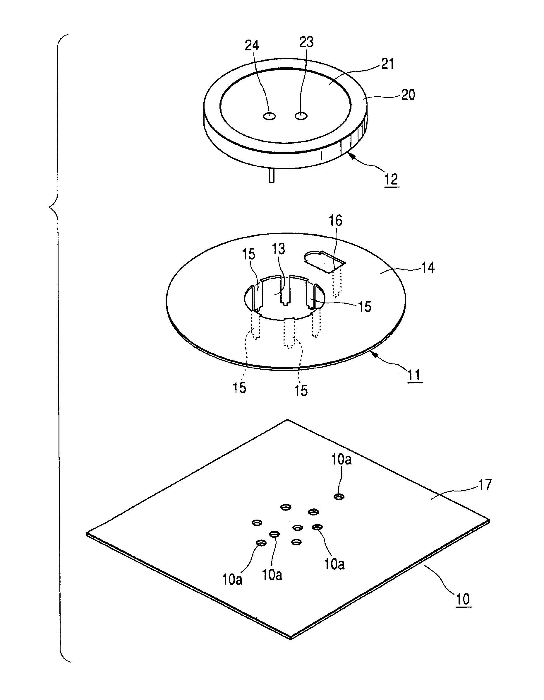
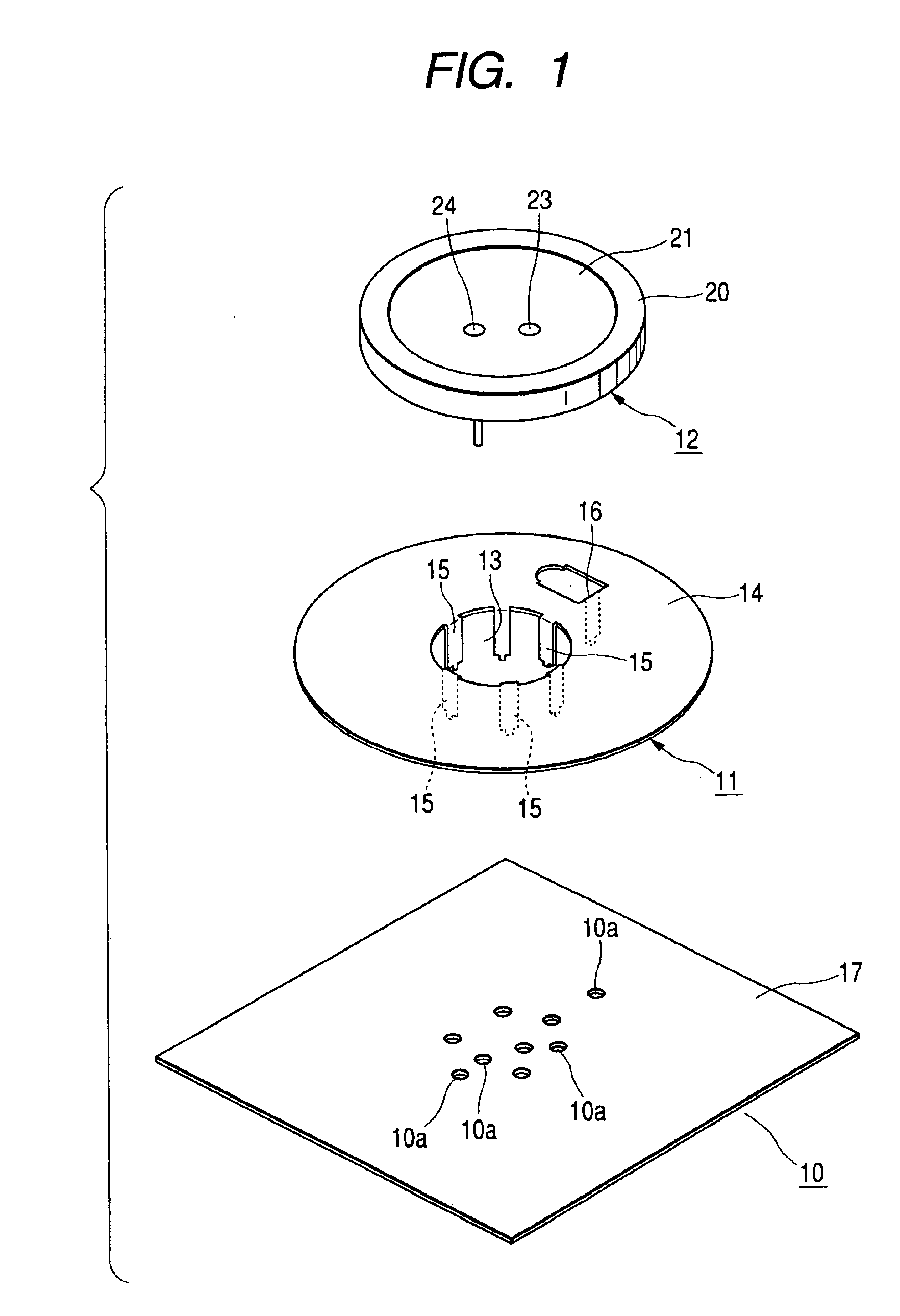
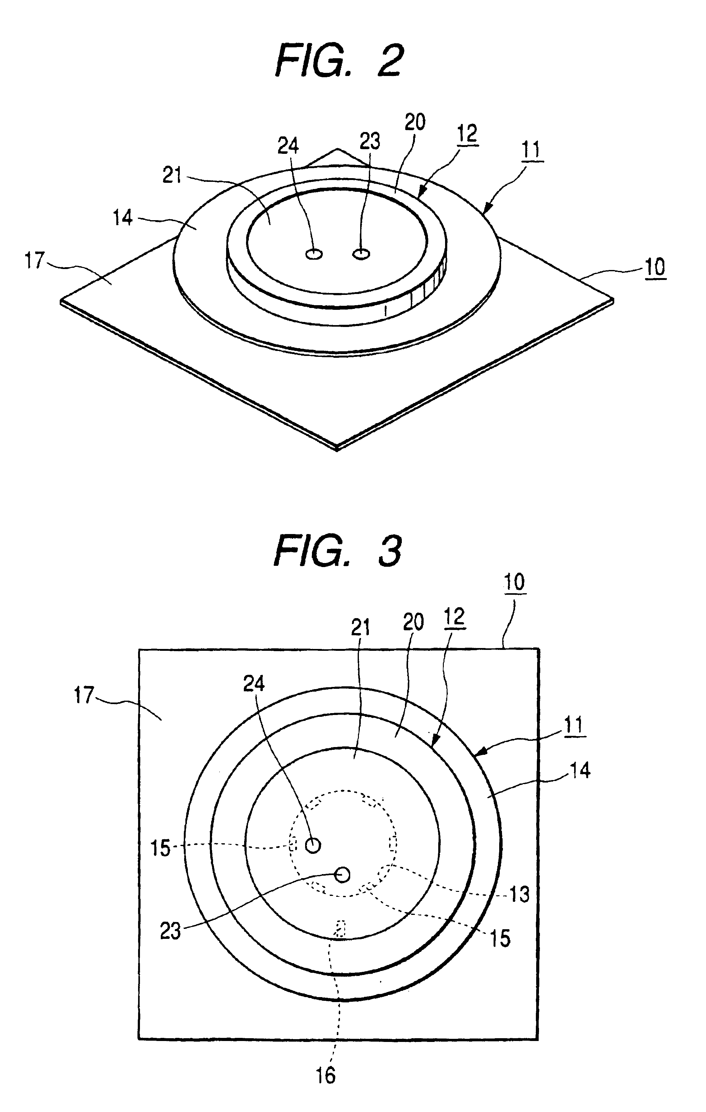
[0016]Hereinafter, an embodiment of the present invention will be described with drawings, wherein FIG. 1 is a exploded perspective view of a combined antenna according to one embodiment of the present invention, FIG. 2 is a perspective view of the combined antenna, FIG. 3 is a top plan view of the combined antenna, and FIG. 4 is a sectional view of the combined antenna.

[0017]The combined antenna shown in the drawings comprises a printed board 10 having a plurality of pass-through holes 10a, a flat plate antenna 11 for ground waves held on the printed board 10, and a patch antenna 12 for satellite waves held on the flat plate antenna 11.

[0018]The flat plate antenna 11 generally includes an annular metallic flat plate 14 having an opening 13 in its center, six ground terminals 15 bent downward from the inner periphery of the metallic flat plate 14, one feed terminal 16 cut up and bent downward from some portion of the metallic flat plate 14, and a ground conductor 17, such as a coppe...


PUM


Abstract

A combined antenna combining a circularly polarized wave antenna and a vertically polarized wave antenna is provided. A flat plate antenna for ground waves is fixed on a printed board, and a two-point feeding type patch antenna is placed and fixed on a metallic flat plate of the plate antenna. The plate antenna has one feed terminal and six uniformly spaced ground terminals. The patch antenna has two feed pins at equidistant positions from the center of the patch electrode along radial lines that form a right angle. Each of feed pins is connected to a 90-degree phase difference circuit using an opening of the plate antenna. The relative position between the flat plate and the patch electrode is the same along the peripheral direction. All of the feed terminals, the ground terminals and the feed pins have a predetermined positional relationship relative to one another.

Description

[0001]This application claims the benefit of priority to Japanese Patent Application No. 2003-139000, herein incorporated by reference.BACKGROUND OF THE INVENTION[0002]1. Field of the Invention[0003]The present invention relates to a combined antenna mounted on a movable body such as an automobile and capable of receiving satellite waves and ground waves.[0004]2. Description of the Related Art[0005]Circularly polarized waves are widely used in systems for receiving satellite broadcasts on a movable body such as an automobile, and in recent years, in order to improve reception in a blind zone such as in the shadow of a building, the use of a satellite broadcast system has been considered to retransmit from the stationary satellite the same contents as the direct broadcast waves. As for the antenna suitable for such a satellite broadcast system, a combined antenna has been suggested having a combined structure including a patch antenna for receiving satellite waves and a helical anten...

Claims


Application Information

Patent Timeline
Patent Type & Authority Patents(United States)
IPC IPC(8): H01Q21/24H01Q9/04H01Q21/28H01Q21/00H01Q13/08
CPCH01Q9/0435H01Q21/28H01Q21/24
Inventor HIGASA, MASAHIKO
Owner ALPS ALPINE CO LTD
Why Eureka
Try Eureka