Functionally strained optical fibers

a technology of functional tension and optical fibers, applied in the field of optical fibers, can solve the problems of increasing the difficulty of tasks using the traditional constant tension per fiber approach, and achieve the effects of reducing attenuation, reducing impact, and optimizing strain distribution

Inactive Publication Date: 2005-05-24
ALCATEL LUCENT SAS
View PDF12 Cites 32 Cited by
  • Summary
  • Abstract
  • Description
  • Claims
  • Application Information

AI Technical Summary

Benefits of technology

[0011]The present invention is directed to eliminating or greatly reducing the impact of the above problems by the use of non-uniform tensile loads on individual fibers during the ribbonizing process to adjust or alter the strain and EFL in the fibers and to create flat or geometrically stable curved ribbons with optimized strain distribution and reduced attenuation. This invention introduces a new concept of “smart” ribbon which may have flat or bowed cross section and is straight along the length or curved in its plane, or twisted unidirec

Problems solved by technology

This task becomes increasingly difficult using the traditional constant ten

Method used


Image

  • Functionally strained optical fibers
  • Functionally strained optical fibers
  • Functionally strained optical fibers

Examples


first embodiment

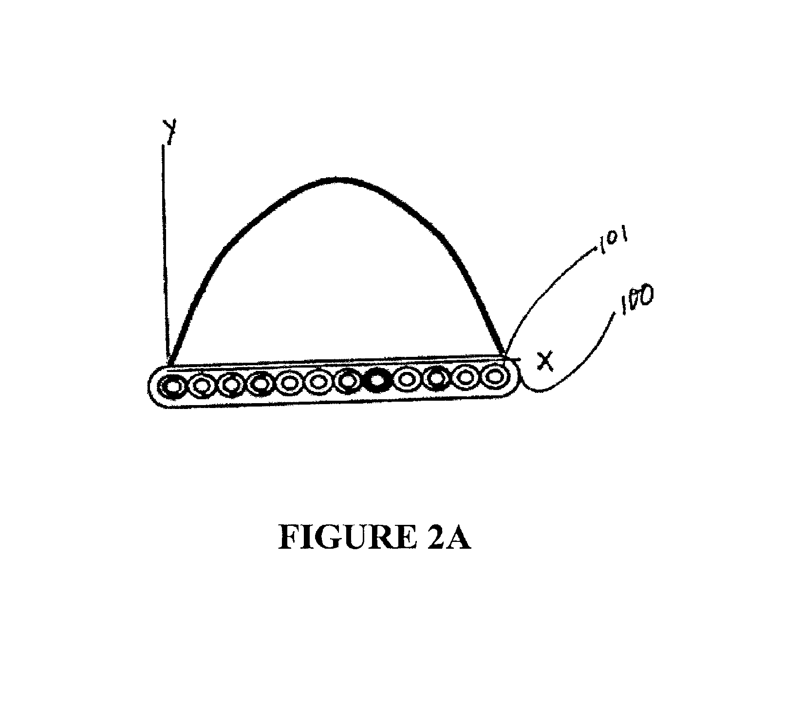
[0027]Turning now to FIGS. 2A through 2E, in the invention various tension functions for fiber stress during ribbon manufacture are shown. In FIG. 2A, a typical fiber optic ribbon 100 is shown along the X-axis of a graph, having a plurality (twelve) optical fibers 101. The Y-axis of the graph represents the tensile force applied to the individual optical fibers along the width of the fiber during manufacture. In this Figure, a symmetric parabolic or sinusoidal curve is shown where the tensile load on the end fibers is less than that on the center most fibers, while the fibers are being drawn. In the preferred embodiment of the present invention, the exact tensile load values and the function of the distribution over the fibers should be such as to result in a flat or otherwise geometrically stable ribbon after manufacture. Therefore, the exact loads and distribution to be used is to be tailored to the particular manufacturing process being used, because no one load distribution woul...

second embodiment

[0040]As shown in FIG. 4, the optical fiber ribbon 100 is made up of three sub-unit ribbons 20, 22, 24. Each sub-unit ribbon 20, 22, 24 is made up of a plurality of optical fibers 10. The optical fiber ribbons 10 of each sub-unit ribbon 20, 22, 24 are then each encased in a matrix material 30, such as a coating resin. The use of multiple sub-units ribbons 20, 22, 24 each encased in separate matrices allows the optical fiber ribbon 100 to be split into the individual sub-unit ribbons 20, 22, 24, if necessary.

[0041]Next, each of the sub-unit ribbons 20, 22, 24 is pre-stretched by a tension load that is constant for the entire the sub-unit 10, 12, 14. These sub-unit ribbons 10, 12, 14 are then encased in a common matrix material 32 to form the final optical fiber ribbon 100.

[0042]As shown in FIG. 5A, in a first configuration, the individual sub-unit ribbons 20, 22, 24 are provided with symmetrical tension loads before they are encased to form the optical fiber ribbon 100. A first tensi...


PUM


Abstract

The present invention introduces a concept of “smart” ribbons, which use functionally tensioned optical fibers during the manufacture of fiber optic ribbons to create fiber ribbons with controlled geometrical configuration, optimized strain distribution and reduced attenuation. The ribbons may have flat or bowed cross section and be straight along the length or curved in its plane, or twisted unidirectionally, or periodically. These shapes and residual stress-strain state are induced and controlled by using tension functions instead of traditional constant-value tension per fiber during the ribbon manufacture. Further, the present invention reduces signal loss and/or attenuation in ribbon fibers caused by an increase in the strain variation from tensile strain to compressive strain along the length of the individual fibers when ribbons are manufactured, stacked, stranded around a strength member or twisted and bent during cable installation. In a first embodiment of the present invention, either a symmetric or non-symmetric load distribution is applied across the fibers being placed or drawn into a ribbon structure to eliminate or control residual twist in a completed fiber ribbon. Additionally, in the present invention, the load distribution on the fibers of a ribbon can be varied (e.g. periodically changed) along the length of the ribbon to provide a ribbon with the required design characteristics for any particular application. In a second embodiment of the invention, a fiber optic ribbon is made up of a plurality of sub-unit ribbons arranged in substantially the same plane. Each sub-unit ribbon includes a plurality of optical fibers coated by sub-unit matrices.

Description

[0001]This application is a continuation-in-part of application Ser. No. 09 / 916,327 filed on Jul. 30, 2001 now abandoned, the disclosure of which in incorporated herein by reference.FIELD OF THE INVENTION[0002]The present invention generally relates to the field of optical fibers, in particular to the manufacture of fiber optic ribbons with functionally tensioned fibers to form ribbons with controlled geometrical configuration, optimized strain distribution and reduced attenuation. This invention introduces a new concept of “smart” ribbon which may have flat or bowed cross section and is straight along the length or curved in its plane, or twisted unidirectionally, or periodically. These shapes and residual stress-strain states are induced and controlled by using tension functions instead of traditional constant-value tension per fiber during the ribbon manufacture.Discussion of Related Art[0003]Optical fibers are very small diameter glass strands which are capable of transmitting a...

Claims


Application Information

Patent Timeline
IPC IPC(8): B29D11/00G02B6/44
CPCG02B6/448B29D11/00663
Inventor JOHNSON, CHRISTOPHER L.NECHITAILO, NICHOLAS V.
Owner ALCATEL LUCENT SAS
Why Eureka
Try Eureka