
A strain-induced semi-solid forming device and process for a fine-grained bearing bush

A strain-induced, semi-solid technology, applied in the direction of swage forging presses, upsetting forging presses, metal extrusion dies, etc., can solve the problems of low welding strength, low strength, high cost, etc., and achieve improved strain distribution and device design Reasonable, good deformation effect

Inactive Publication Date: 2016-11-09
XI AN JIAOTONG UNIV
View PDF5 Cites 0 Cited by
  • Summary
  • Abstract
  • Description
  • Claims
  • Application Information

AI Technical Summary

Problems solved by technology

At present, the two types of bearing materials mainly used in automobile engine bearings are copper-based and aluminum-based alloys. Aluminum-based bearing materials are widely used because of their superior thermal conductivity and corrosion resistance, but their strength is relatively low. The best way is to use a certain method to compound the aluminum-based alloy on the steel base plate to form a steel-backed aluminum-based bimetallic composite plate to make up for the shortcomings of the aluminum-based alloy’s insufficient strength and hardness. Then, the steel-backed aluminum-based bimetallic composite plate The composite plate is rolled and welded into a cylinder, and then the bearing bush is machined into shape
This method can well make up for the shortcomings of insufficient strength and hardness of aluminum-based alloys, but there are still poor wear resistance of aluminum-based alloys, the interface bonding strength of composite plates is not easy to control, the welding strength of steel plates after welding into cylinders is not high, and the follow-up machine Disadvantages such as difficult processing, complex manufacturing process of the entire bearing bush, and high cost

Method used


Image

  • A strain-induced semi-solid forming device and process for a fine-grained bearing bush
  • A strain-induced semi-solid forming device and process for a fine-grained bearing bush
  • A strain-induced semi-solid forming device and process for a fine-grained bearing bush

Examples


Embodiment Construction

[0044] The present invention will be described in detail below in conjunction with the accompanying drawings.

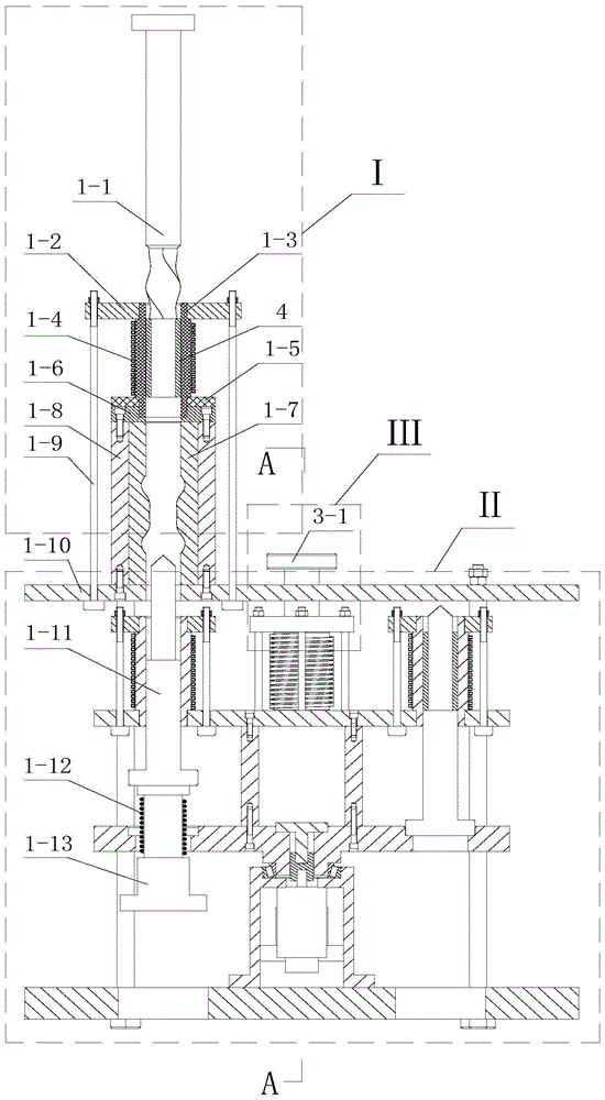
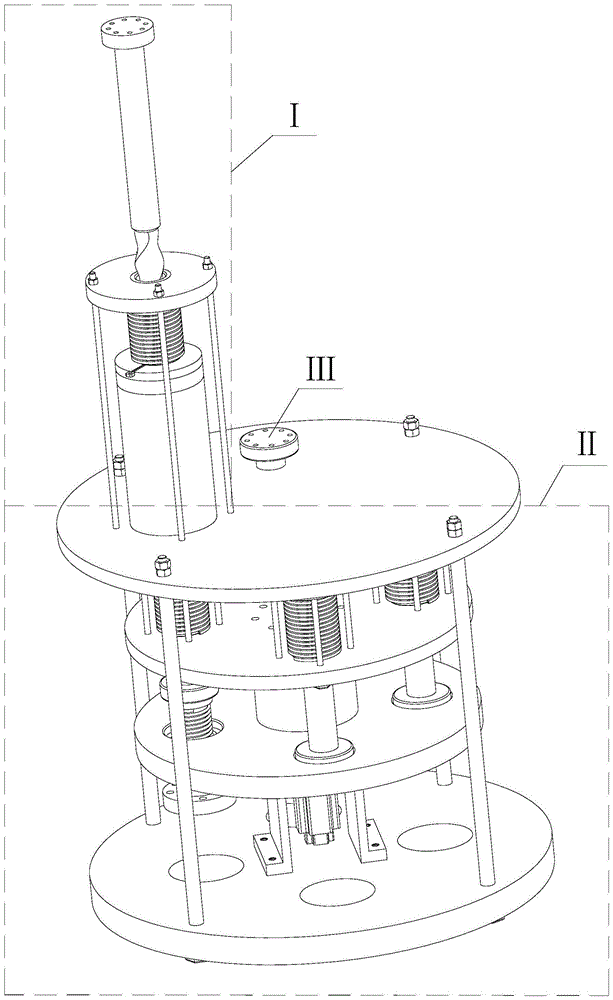
[0045] refer to figure 1 and figure 2 , a strain-induced semi-solid forming device for fine-grained bearing bushes, including three parts: pre-deformation device I, intermediate frequency heating and rotating device II, and semi-solid upsetting device III, wherein pre-deformation device I is fixedly installed on the intermediate frequency heating and rotating device Above II, the semi-solid upsetting device III is located at the left rear of the pre-deformation device I, and the semi-solid upsetting device III moves up and down in the intermediate frequency heating rotating device II.

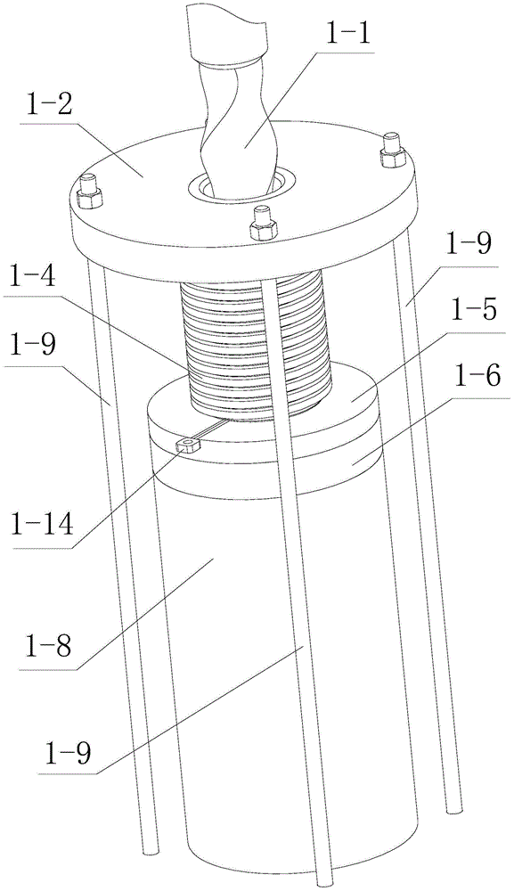
[0046] refer to figure 1 , image 3 , Figure 7 and Figure 8 The pre-deformation device I includes a blank push rod 1-1 located at the top of the pre-deformation device I, the lower end surface of the blank push rod 1-1 is in contact with the upper end surface of the bearing pa...


PUM


Abstract

The invention discloses a strain-induced semi-solid forming device and a strain-induced semi-solid forming process for a fine-grained bearing pad. The device comprises three major parts, namely a pre-deformation device, a medium-frequency heating rotating device and a semi-solid upsetting device, wherein the pre-deformation device is fixedly arranged above the medium-frequency heating rotating device; the semi-solid upsetting device is positioned behind the left part of the pre-deformation device, and moves up and down in the medium-frequency heating rotating device. In the corresponding process, the device is used for sequentially performing blank pre-deformation treatment on a blank, performing semi-solid heat-preservation treatment on the deformed blank and performing upsetting treatment on the semi-solid blank. The device is reasonable in design, the process is easy to operate, a formed bearing pad part has good characteristics of a fine-grained structure and high comprehensive performance, and can be automatically and continuously produced, the production efficiency of the bearing pad is effectively improved, and the production cost of the bearing pad is lowered.

Description

technical field [0001] The invention belongs to the technical field of metal semi-solid forming, and in particular relates to a strain-induced semi-solid forming device and process of fine-grain structure bearing bushes. Background technique [0002] Semi-solid metal forming is an emerging metal forming technology. Its spherical or nearly spherical semi-solid slurry has the advantages of good fluidity, low forming force and good performance of the formed parts. Therefore, it is applied to improve the overall The comprehensive performance of aluminum-based or copper-based bearing pads has practical application significance. The strain-induced melting activation method (SIMA) is a method for preparing semi-solid metal billets firstly proposed by Young et al. Dendrite structure, and then carry out a small amount of cold deformation on the thermally deformed blank to store a certain denaturation in the structure, then divide the deformed blank into target sizes, and finally hea...

Claims


Application Information

Patent Timeline
Patent Type & Authority Patents(China)
IPC IPC(8): B23P15/00B21C23/21B21C25/02B21C29/00B21J9/06
CPCB21J1/025B21J1/06B21J5/004
Inventor 赵升吨王永飞张晨阳韩晓兰赵永强
Owner XI AN JIAOTONG UNIV
Learn More