Quasiturbine (Qurbine) rotor with central annular support and ventilation

a rotor and annular support technology, applied in the direction of rotary or oscillating piston engines, rotary piston engines, differential gearings, etc., can solve the problems of critical and difficult sealing problems of five-bodies, and achieve the effects of reducing flow turbulence, minimizing surface to volume ratio, and low friction

Inactive Publication Date: 2005-05-31
SAINT HILAIRE ROXAN +3
View PDF13 Cites 49 Cited by
  • Summary
  • Abstract
  • Description
  • Claims
  • Application Information

AI Technical Summary

Benefits of technology

[0008]Another object of this invention is to provide a “Saint-Hilaire confinement profile calculation method” of the internal contoured housing wall appropriate to the chosen Quasiturbine design arrangement, minimizing the surface to volume ratio in the compression chambers and reducing the flow turbulence. This calculation method includes criteria for engine optimum confinement profile selection from the family of curves to generate the internal contoured housing wall.
[0009]A further object of this inv...

Problems solved by technology

In most rotary engines, the sealing at the pivot connection or apex between two adjacent blades must be done simultaneously with the internal contoured housing wall and also with the two lateral side covers which is a critical and difficult five-bodies sealing problem.
The following rotary engine prior arts, either ignored the need or fail to provide the necessary strong mechanism needed to withstand the radial high pressu...

Method used


Image

  • Quasiturbine (Qurbine) rotor with central annular support and ventilation
  • Quasiturbine (Qurbine) rotor with central annular support and ventilation
  • Quasiturbine (Qurbine) rotor with central annular support and ventilation

Examples


Embodiment Construction

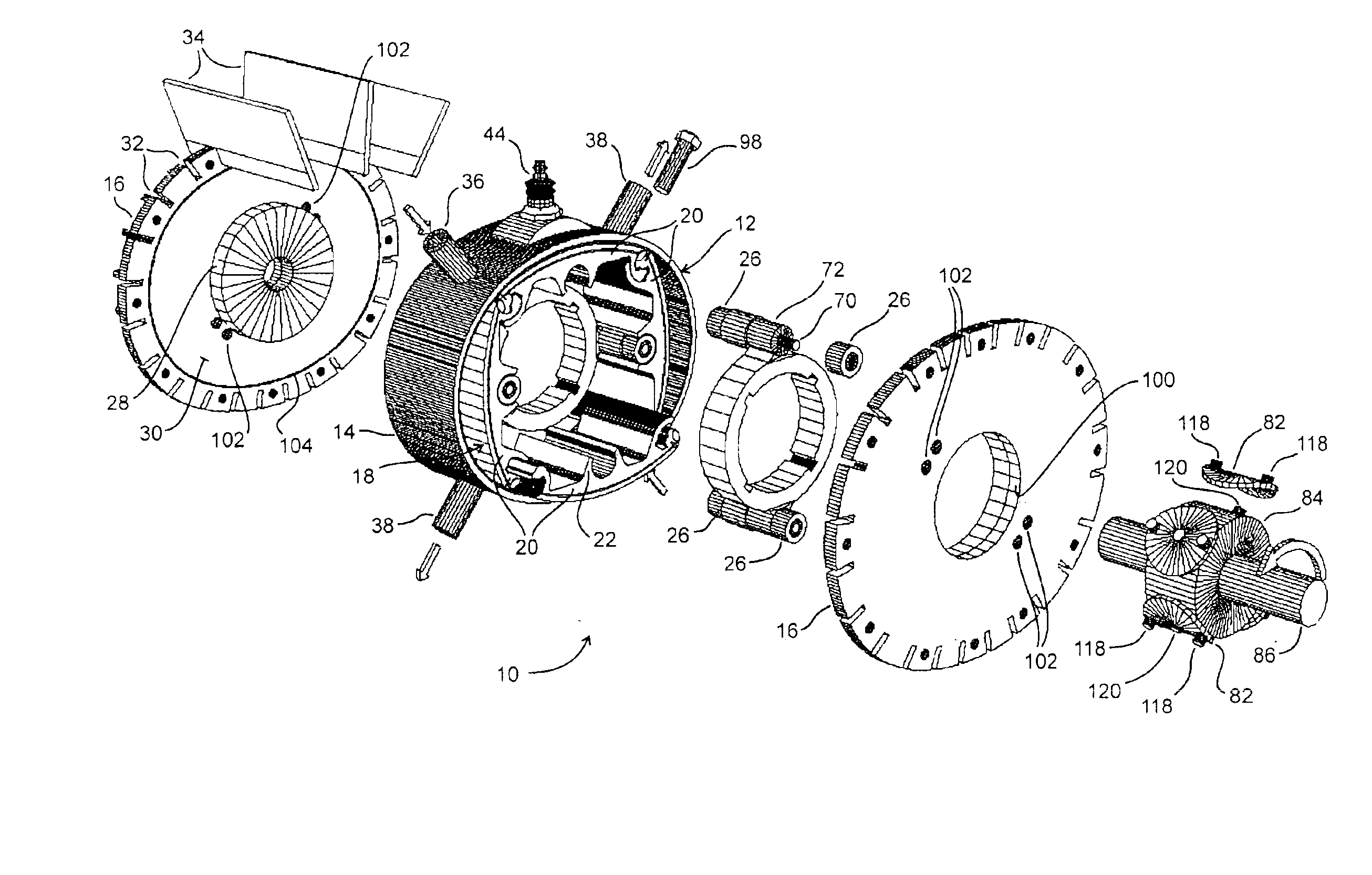
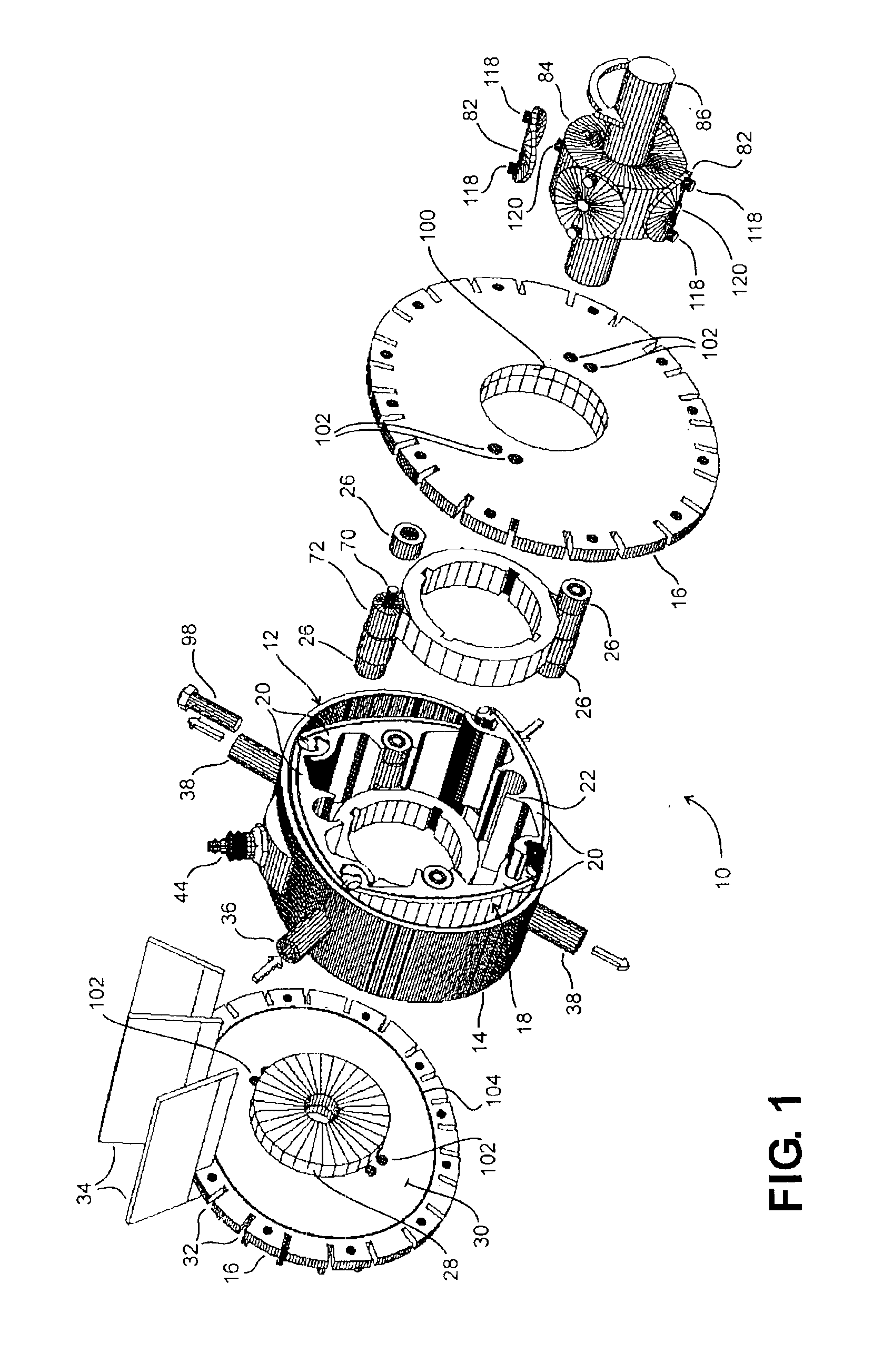
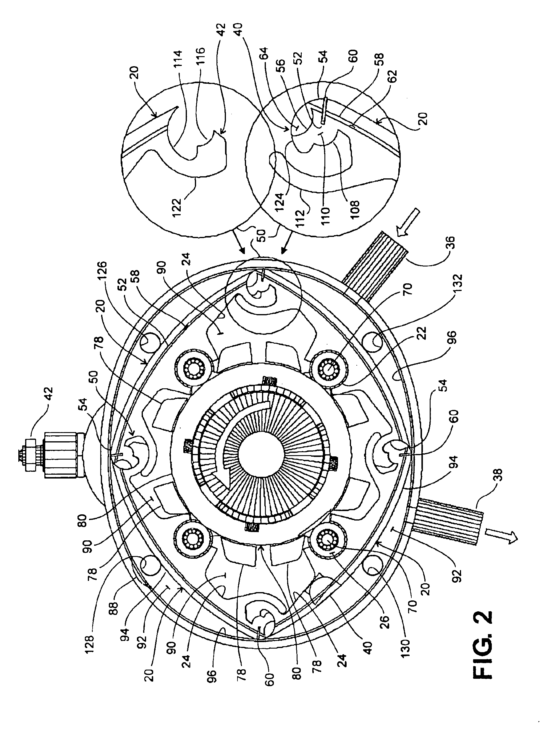
[0017]The U.S. Pat. No. 6,164,263 patent disclosed a Quasiturbine rotor arrangement using four rolling carriages to take the pivoting blade pressure-load and transfer it to the opposite internal contoured housing wall. The present invention discloses a Quasiturbine rotor arrangement without carriages, where the pressure-load on each pivoting blade is taken by its own set of wheel-bearings located in a power transfer slot in the inner side of blade, the wheel-bearings rolling on annular tracks, one track attached to the central area of each lateral side cover. This rotor supporting configuration can apply to all the Quasiturbine family of designs, and is here illustrated on a specific Quasiturbine embodiment without rolling carriages. This Quasiturbine rotor arrangement reduces the number of components, reduces the friction surface, reduces the total wall surface in the compression chambers, and is particularly suitable for non-metallic pivoting blades, the blades being made instead ...


PUM


Abstract

The Quasiturbine (Qurbine in short) uses a rotor arrangement peripherally supported by four rolling carriages, the carriages taking the pivoting blade pressure-load of the blades forming the rotor, and transferring the load to the opposite internal contoured housing wall. The present invention discloses a central, annular, rotor support for the rotor geometry defined by the pivoting blades and associated wheel-bearings, while still maintaining the important center-free engine characteristic. The pressure-load on each pivoting blade is taken by its own set of wheel-bearings rolling on annular tracks attached to the central area of the lateral side covers forming part of the stator casing. This central, annular, rotor support could generally apply to all the family of Quasiturbine rotor arrangements and particularly to the limit case here considered, where the previous carriage design is replaced by a cylindrical pivoting blade joint as presented in the present patent, and for which an efficient solution of the five bodies rotary engine sealing problem is given.

Description

[0001]This application claims benefit of U.S. Provisional Application No. 60 / 366,298, filed on Mar. 22, 2002.FIELD OF THE INVENTION[0002]This invention relates generally to a perfectly balanced, zero vibration, rotary device, and specifically to rotary engines, compressors, and pressure or vacuum pumps.DESCRIPTION OF THE RELATED ART[0003]The patent U.S. Pat. No. 6,164,263 discloses a general rotary device called the Quasiturbine (Qurbine in short), which uses four pivoting blades and four rolling carriages to make a rotor of variable diamond-shaped geometry, the rotor mounted within a internal contoured housing wall formed along a Saint-Hilaire confinement profile shaped somewhat like a skating rink, the sides of the internal contoured housing wall closed by lateral side covers. That Quasiturbine device uses four peripheral rolling carriages to hold the rotor in place within the internal contoured housing wall and to transfer the pivoting blade radial load-pressure to the opposite p...

Claims


Application Information

Patent Timeline
IPC IPC(8): F02B55/00F02B55/02F02B55/14F02B53/00
CPCF02B55/14F02B55/02F02B53/00
Inventor SAINT-HILAIRE, ROXANSAINT-HILAIRE, YLIANSAINT-HILAIRE, GILLESSAINT-HILAIRE, FRAN.CEDILLA.OISE
Owner SAINT HILAIRE ROXAN
Why Eureka
Try Eureka