Device and method for controlling/balancing flow fluid flow-volume rate in flow channels

a flow channel and flow control technology, applied in the direction of domestic stoves or ranges, heating types, separation processes, etc., can solve problems such as aerosol precipitation, and achieve the effect of minimizing steady and quasi-steady flow effects

Inactive Publication Date: 2005-05-31
HALTON GROUP LTD
View PDF14 Cites 64 Cited by
  • Summary
  • Abstract
  • Description
  • Claims
  • Application Information

AI Technical Summary

Benefits of technology

[0009]Briefly, flow control devices located either within a duct or inside a hood recess enable the control of the relative exhaust volume flow rates through sections of a long exhaust hood or through separate hoods linked to a single exhaust fan. In one embodiment, flow control devices are located inside the ducts. Although using flow control devices in a duct is known, conventional flow control devices, known as “dampers,” cause aerosol precipitation in exhaust ducts of kitchen ventilation systems and are therefore not used. To address this problem, the latter flow control devices are shaped to minimize steady and quasi-steady flow effects associated with the precipitation of grease from the aerosol state. In another embodiment, the flow control devices are located within the hood recess so that any precipitation that occurs as a result of the steady flow structures will remain within the recess and can be cleaned easily. Both types of flow control devices must be designed differently from conventional dampers. Flow control devices within the ducts are designed to restrict flow without forming flow effects that result in the precipitation of grease. Flow control devices within the canopy recess are designed such that they do not interfere with the vortical flow effect caused by the thermal convection plume. Each device may be adjustable or fixed, but preferably they are adjustable in applications where perfectly uniform negative pressures in the building exhaust hookups cannot be guaranteed.

Problems solved by technology

Although using flow control devices in a duct is known, conventional flow control devices, known as “dampers,” cause aerosol precipitation in exhaust ducts of kitchen ventilation systems and are therefore not used.

Method used


Image

  • Device and method for controlling/balancing flow fluid flow-volume rate in flow channels
  • Device and method for controlling/balancing flow fluid flow-volume rate in flow channels
  • Device and method for controlling/balancing flow fluid flow-volume rate in flow channels

Examples


Embodiment Construction

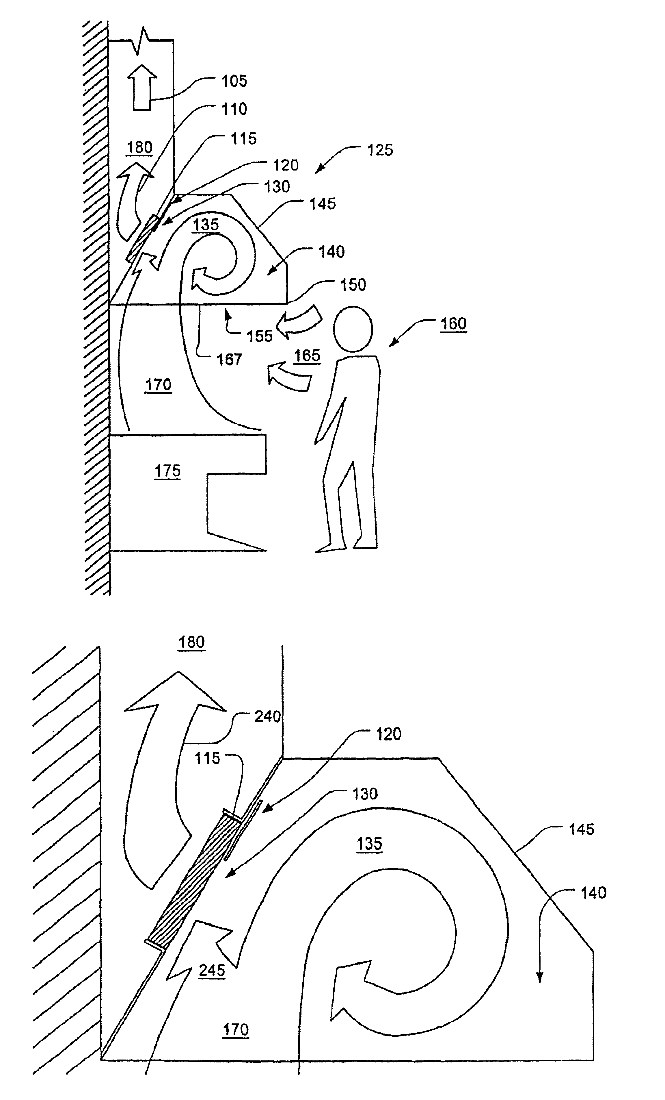
[0083]Referring to FIG. 4, a kitchen hood 125 has a canopy 145 positioned over a heat / contaminant source 175 (such as a grill) to capture a thermal convection plume 170 produced by the heat / contaminant source 175. The canopy 145 defines a recess 140, having an access 155. An exhaust fan (not shown) draws a flue stream 105 through an exhaust plenum 180. Negative pressure in the exhaust duct 180 in turn draws gases residing in the recess 140 through a vent 130. In the vent 130 is a mechanical grease filter 115, set in a boundary wall 120 that defines part of the recess 140. The filter reduces the mass of suspended grease particles in the resulting flue stream. The grease filter 115 may be an impingement filter or one based on cyclone type separation principles. The thermal convection plume 170 carries pollutants and air upwardly into the canopy recess 140 by buoyancy forces combined with forced convection resulting from the suction created by the exhaust fan. A combined effluent strea...


PUM

PropertyMeasurementUnit
flow resistanceaaaaaaaaaa
diameteraaaaaaaaaa
flexibleaaaaaaaaaa

Abstract

A system and method for controlling flow in filtering systems and for balancing the flow through fluid systems employs flow control devices that minimize suspended matter precipitation. Several embodiments are included. In a first embodiment, a smooth-walled flow control device (410) with no abrupt transitions is provided in a flow conduit section. In a second embodiment, a filter (305) acts as a flow control device. A variation of the latter locates a flow control device (300) immediately adjacent to the filter (305) and upstream of it. In other embodiments, a control system (950) detects the real time status of the load to provide on the fly critical balancing.

Description

[0001]This application claims benefit of provisional No. 60 / 224,123 filed Aug. 10, 2000, Ser. No. 60 / 226,953 filed Aug. 22, 2000 and Ser. No. 60 / 263,557 filed Jan. 23, 2001.FIELD OF THE INVENTION[0002]The present invention relates generally to flow-volume control devices. More specifically, the present invention relates to flow control devices that may be used for balancing fluid flow in a context where suspended particles are entrained in the fluid and their precipitation must be avoided, in free-flowing parts of a flow system, except during filtration.BACKGROUND[0003]Exhaust hoods are used to remove air contaminants close to the source of generation located in a conditioned space. For example, one type of exhaust hoods, kitchen range hoods, creates suction zones directly above ranges, fryers, or other sources of air contamination. Exhaust hoods tend to waste energy because they must draw some air out of a conditioned space in order to insure that all the contaminants are removed. ...

Claims


Application Information

Patent Timeline
Patent Type & Authority Patents(United States)
IPC IPC(8): F24C15/20B01D45/00B01D46/00F15D1/02
CPCF15D1/02F24C15/2035F24C15/20
Inventor LIVCHAK, ANDREYSCHROCK, DEREK
Owner HALTON GROUP LTD
Why Eureka
Try Eureka