Switching valve seal

a technology of switching valve and sealing valve, which is applied in the direction of lighting and heating apparatus, combustion types, furnaces, etc., can solve the problems of valve wear, disturbance and fluctuation of pressure and/or flow in the system, and reduce the efficiency of the apparatus, so as to improve the sealing effect, minimize wear, and improve the sealing

Inactive Publication Date: 2005-05-31
DURR SYST INC
View PDF82 Cites 7 Cited by
  • Summary
  • Abstract
  • Description
  • Claims
  • Application Information

AI Technical Summary

Benefits of technology

[0009]The problems of the prior art have been overcome by the present invention, which provides an improved seal for a single switching valve, and a regenerative thermal oxidizer including the switching valve. The valve of the present invention exhibits excellent sealing characteristics and minimizes wear. The valve has a seal plate that defines two chambers, each chamber being a flow port that leads to one of two regenerative beds of the oxidizer. The valve also includes a switching flow distributor, which provides alternate channeling of the inlet or outlet process gas to each half of the seal plate. The valve operates between two modes: a stationary mode and a valve movement mode. In the stationary mode, a tight gas seal is used to minimize or prevent process gas leakage. The gas seal also seals during valve movement. The valve is a compact design, thereby eliminating ducting typically required in conventional designs. This provides less volume for the process gas to occupy during cycling, which leads to less dirty process gas left untreated during cycling. Associated baffling minimizes or eliminates untreated process gas leakage across the valve during switchover. The use of a single valve, rather than the two or four conventionally used, significantly reduces the area that requires sealing. The geometry of the switching flow distributor reduces the distance and number of turns the process gas goes through since the flow distributor can be located close to the heat exchange beds. This reduces the volume of trapped, untreated gas during valve switching. Since the process gas passes through the same valve ports in the inlet cycle as in the outlet cycle, gas distribution to the heat exchange beds is improved.
[0010]Valve switching with minimal, pressure fluctuations, excellent sealing, and minimal or no bypass during switching are achieved in regenerative thermal oxidation applications. In view of the elimination of bypass during switching, the conventional entrapment chambers used to store the volume of unprocessed gas in the system during switching can be eliminated, thereby saving substantial costs.

Problems solved by technology

Any leakage of untreated process gas through the valve system will decrease the efficiency of the apparatus.
In addition, disturbances and fluctuations in the pressure and / or flow in the system can be caused during valve switchover and are undesirable.
Valve wear is also problematic, especially in view of the high frequency of valve switching in regenerative thermal oxidizer applications.
Although poppet valves exhibit quick actuation, as the valves are being switched during a cycle, leakage of untreated process gas across the valves inevitably occurs.
Since there is also ducting associated with the valving system, the volume of untreated gas both within the poppet valve housing and within the associated ducting represents potential leakage volume.
Since leakage of untreated process gas across the valves leaves allows the gas to be exhausted from the device untreated, such leakage which will substantially reduce the destruction efficiency of the apparatus.
In addition, conventional valve designs result in a pressure surge during switchover, which exasperates this leakage potential.
Similar leakage potential exists with conventional rotary valve systems.
Moreover, such rotary valve systems typically include many internal dividers, which can leak over time, and are expensive to construct and maintain.

Method used


Image

  • Switching valve seal
  • Switching valve seal
  • Switching valve seal

Examples


Embodiment Construction

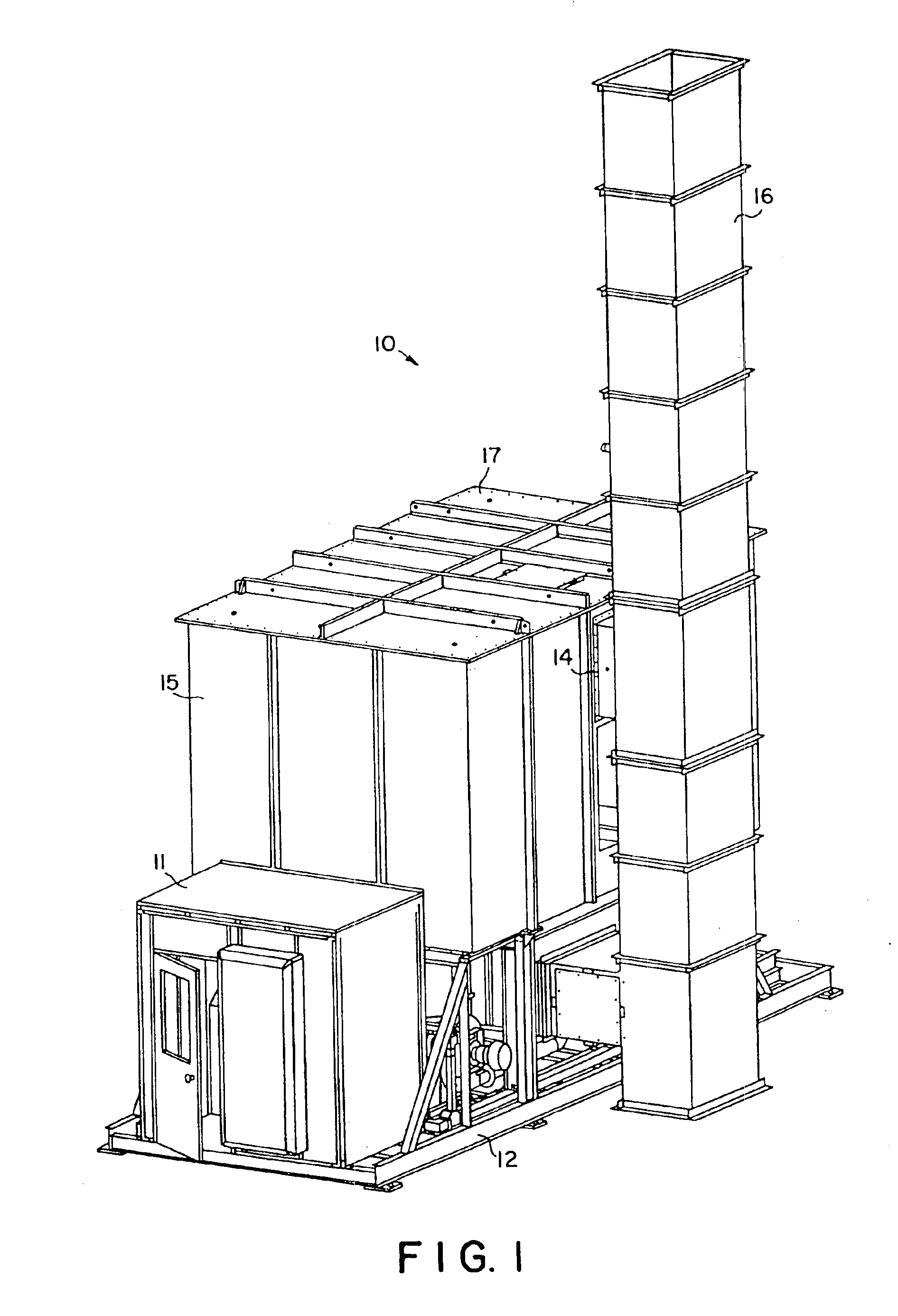
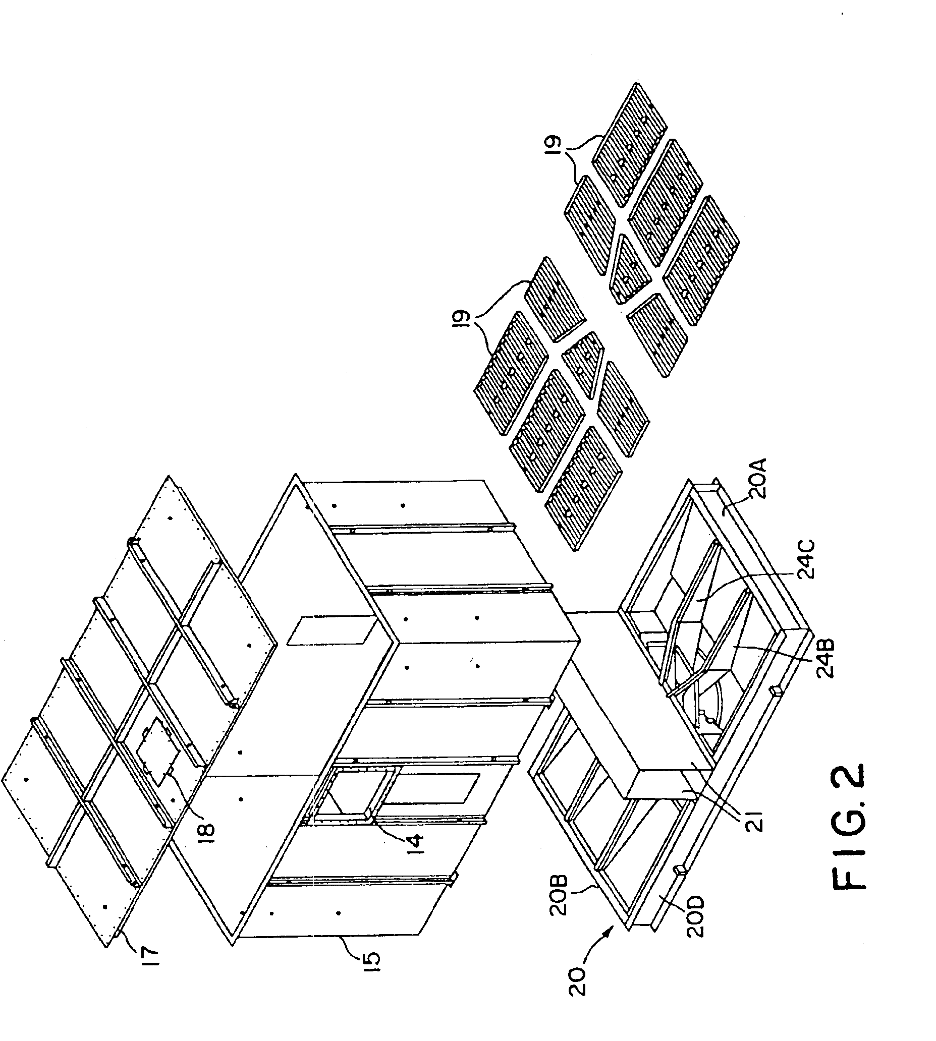
[0038]Turning first to FIGS. 1 and 2, there is shown a two-chamber regenerative thermal oxidizer 10 (catalytic or noncatalytic) supported on a frame 12 as shown. The oxidizer 10 includes a housing 15 in which there are first and second heat exchanger chambers in communication with a centrally located combustion zone. A burner (not shown) may be associated with the combustion zone, and a combustion blower may be supported on the frame 12 to supply combustion air to the burner. The combustion zone includes a bypass outlet 14 in fluid communication with exhaust stack 16 typically leading to atmosphere. A control cabinet 11 houses the controls for the apparatus and is also preferably located on frame 12. Opposite control cabinet 11 is a fan (not shown) supported on frame 12 for driving the process gas into the oxidizer 10. Housing 15 includes a top chamber or roof 17 having one or more access doors 18 providing operator access into the housing 15. Those skilled in the art will appreciat...


PUM


Abstract

Switching valve utilizing a rotatable seal suitable for use in a regenerative thermal oxidizer, and oxidizer including the switching valve. The valve of the present invention exhibits excellent sealing characteristics and minimizes wear. The valve has a seal plate that defines two chambers, each chamber being a flow port that leads to one of two regenerative beds of the oxidizer. The valve also includes a switching flow distributor that provides alternate channeling of the inlet or outlet process gas to each half of the seal plate. The valve operates between two modes: a stationary mode and a valve movement mode. In the stationary mode, a tight gas seal is used to minimize or prevent process gas leakage. The gas seal also seals during valve movement.

Description

[0001]This is a division, of application Ser. No. 09 / 849,785, filed May 4, 2001 now U.S. Pat. No. 6,749,815.BACKGROUND OF THE INVENTION[0002]Regenerative thermal oxidizers are conventionally used for destroying volatile organic compounds (VOC's) in high flow, low concentration emissions from industrial and power plants. Such oxidizers typically require high oxidation temperatures in order to achieve high VOC destruction. To achieve high heat recovery efficiency, the “dirty” process gas that is to be treated is preheated before oxidation. A heat exchanger column is typically provided to preheat these gases. The column is usually packed with a heat exchange material having good thermal and mechanical stability and sufficient thermal mass. In operation, the process gas is fed through a previously heated heat exchanger column, which, in turn, heats the process gas to a temperature approaching or attaining its VOC oxidation temperature. This pre-heated process gas is then directed into a...

Claims


Application Information

Patent Timeline
Patent Type & Authority Patents(United States)
IPC IPC(8): F27D17/00F27D23/00F16K3/06F16K1/00F16K31/53F23M20/00F27D99/00
CPCF23G7/068F23L15/02F27D17/008F27D2099/0048F27D2017/007Y10T137/5689F27D17/00Y02E20/34
Inventor CASH, JAMES T.
Owner DURR SYST INC
Why Eureka
Try Eureka