Grinding machine

Inactive Publication Date: 2005-05-31
HELMUT GEGENHEIMER
View PDF7 Cites 6 Cited by
  • Summary
  • Abstract
  • Description
  • Claims
  • Application Information

AI Technical Summary

Benefits of technology

[0008]In particular when the grinding machine according to the invention is constructed as a liquid grinding machine with a liquid process medium contained in the container, according to a preferred construction the entire disk is rigid. According to a further development in this case, the width or thickness of the gap is at least {fraction (1 / 10)} mm and as a rule should not exceed 2 mm. It has surprisingly been found that in the case of a centrifugal force sliding grinding machine according to the invention with liquid in the container, the latter is expelled from the gap between the rotary disk and the base of the stationary container and no liquid is located there. This prevents grinding material, together with broken off fragments of larger grinding bodies or wheels passing into this area and consequently bringing about an impairment of the mounting of the disk or the disk driving spindle passing outwards through the base.
[0009]The prevention of the penetration of grinding bodies or fragments thereof or the forcing of the same out of the gap between the rotary disk and the stationary base can be achieved in the case of a dry-working centrifugal force grinding machine, i.e. a dry grinding machine, in that the disk has resilient material, at least on its underside.
[0011]The invention makes it possible to construct very inexpensive, operationally reliable centrifugal force grinding machines, which also permit the use of very fine grinding and / or polishing bodies.
[0017]According to another preferred development the casing is in one piece and in particular the casing and / or container is made from plastic. As a result the grinding machine according to the invention can be manufactured economically and therefore inexpensively. This is helped by the fact that the gear is positioned below the disk. In an alternative construction the drive is constructed as a geared motor with an integrated gear and then in particular the motor with its shaft is vertically oriented and a driven shaft passes out of the lower end of the motor and the top of the motor is essentially at the same level as the top of the container.

Problems solved by technology

This prevents grinding material, together with broken off fragments of larger grinding bodies or wheels passing into this area and consequently bringing about an impairment of the mounting of the disk or the disk driving spindle passing outwards through the base.

Method used


Image

  • Grinding machine
  • Grinding machine
  • Grinding machine

Examples


Embodiment Construction

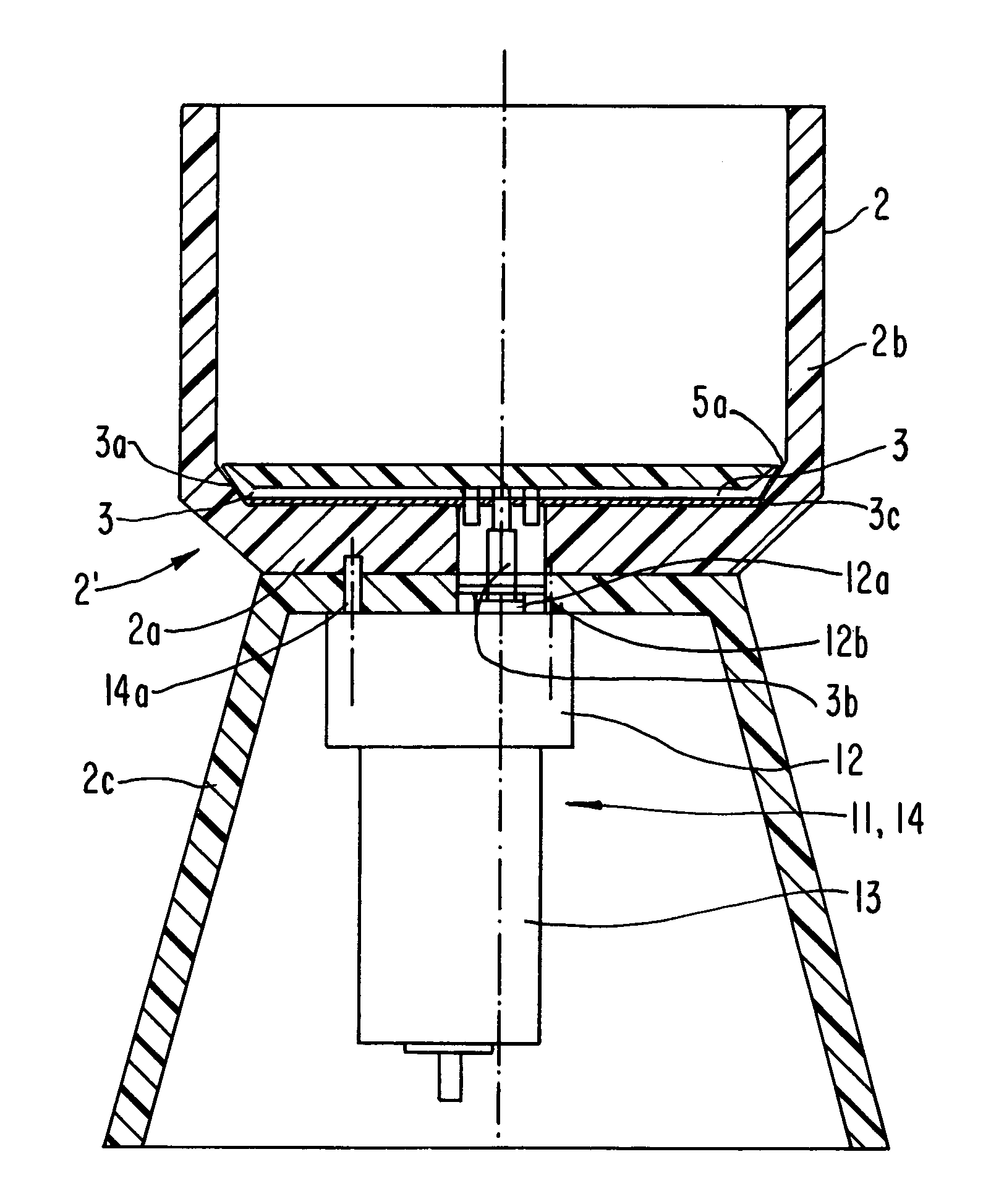
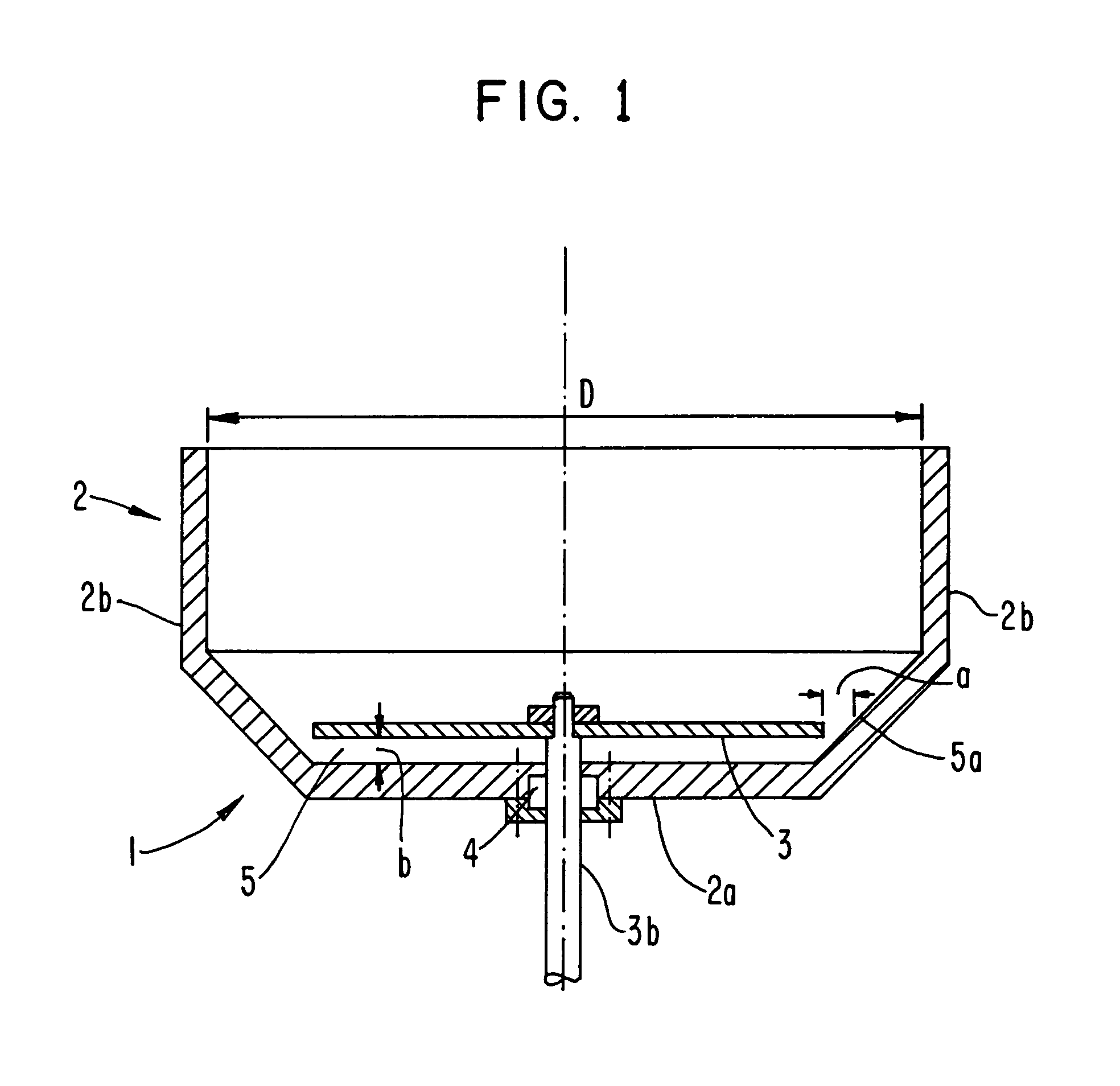
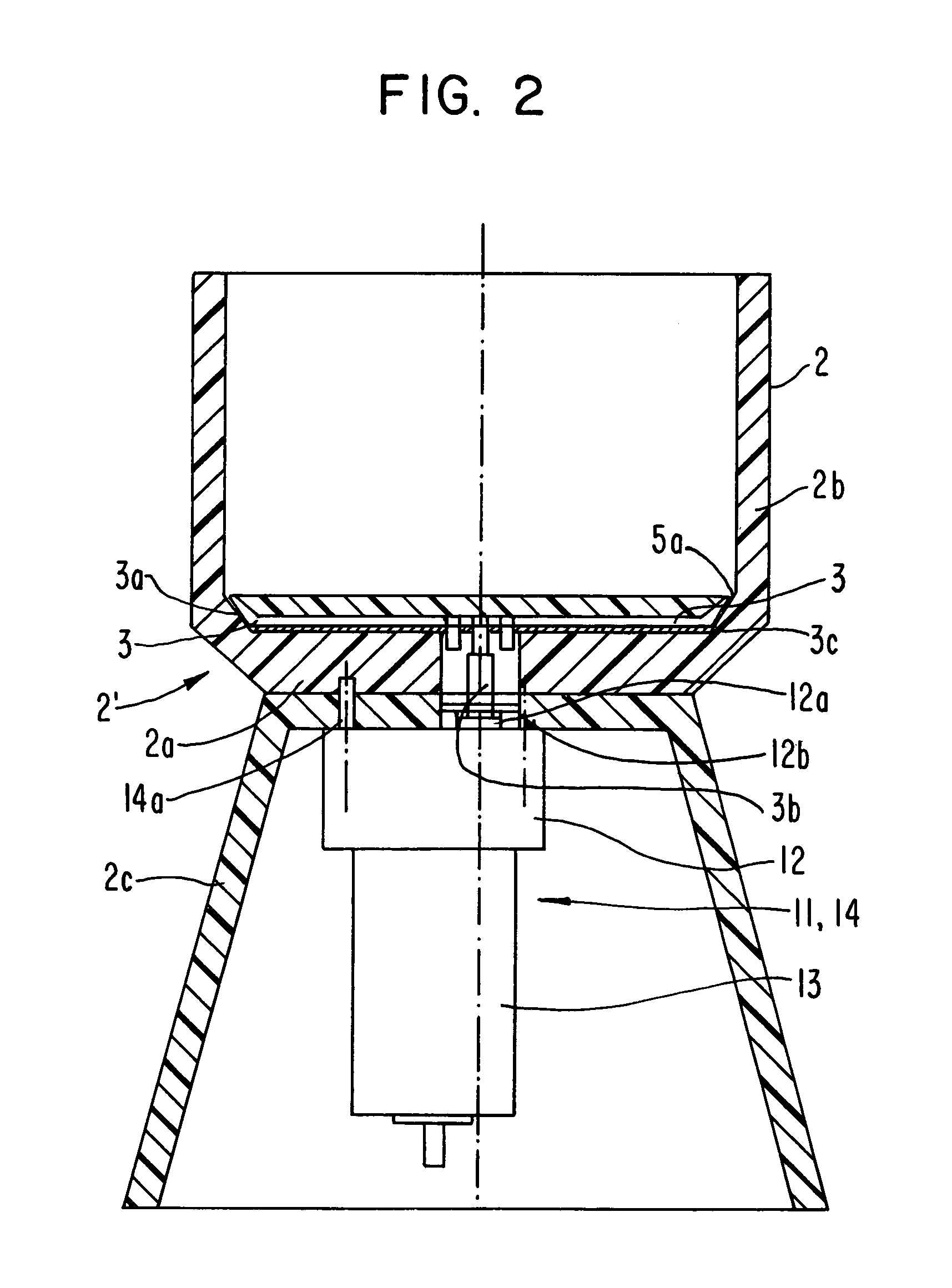
[0024]The grinding 1 of a centrifugal force sliding grinding machine in the form of a disk centrifugal force grinding machine shown in FIG. 1 has a container 2 with a rotary disk 3. If the disk is rigid, working takes place with liquid in the container.

[0025]However, for both wet and dry working, the disk can also be of flexible material, e.g. rubber. The disk is driven by a shaft 3b. The shaft 3b traverses in preferably liquid-tight manner a container base 2a and is mounted in rotary manner thereon by means of bearings 4. Accompanied by the formation of a gap 5, the disk 3 is spaced from the container base 2a and in the case of dry working the gap width b is e.g. approximately 3 mm. The disk 3 and / or container 2 can be positioned in vertically adjustable manner, e.g. accompanied by a variation of the gap width b.

[0026]During the operation of the grinding machine the comparatively wide gap 5 makes it possible for small particles of the grinding material or in particular the grinding...


PUM


Abstract

The invention provides a grinding machine for grinding grinding material by means of grinding bodies or wheels, having at least one grinding unit and two parts rotatable relative thereto, which has a container for receiving grinding material and a rotary disk placed above a container base, accompanied by the formation of a finite gap.

Description

BACKGROUND OF THE INVENTION[0001]The invention relates to a grinding machine for grinding grinding material by means of grinding bodies or wheels, having at least one grinding unit with two parts rotatable relative to one another.[0002]For example centrifugal force sliding grinding machines are known, which comprise a two-part container with a shell-like, rotary container lower part forming a base and a stationary, cylindrical container upper part.[0003]Such grinding machines are used for the surface working of grinding material, e.g. smaller parts and workpieces, which are moved together with the grinding bodies and optionally a liquid process medium in the container. If the lower part is rotated, the workpieces to be treated are moved outwards on the disk until they encounter the inner wall of the container where they are decelerated. Through the subsequently flowing workpieces a revolving workpiece movement occurs, which brings about an intense grinding or polishing.[0004]A parti...

Claims


Application Information

Patent Timeline
IPC IPC(8): B24B31/00B24B31/12B24B31/108
CPCB24B31/12B24B31/108
Inventor LUTZ, HELMUT
Owner HELMUT GEGENHEIMER
Why Eureka
Try Eureka