Plasmapheresis filter device and catheter assembly

a filter device and plasmapheresis technology, applied in the field of plasmapheresis filter devices and catheter assemblies, can solve the problems of inability to perform in-vivo, clogging, and inability to achieve in-vivo satisfactory in-vivo performance of conventional dialysate hollow fiber membrane filters, and achieves the effect of higher mass density and low mass density

Inactive Publication Date: 2005-05-31
TRANSVIVO
View PDF24 Cites 13 Cited by
  • Summary
  • Abstract
  • Description
  • Claims
  • Application Information

AI Technical Summary

Problems solved by technology

Conventional hollow fibers or filter membranes such as those used in dialysate filter devices are unable to successfully perform in-vivo, intravascular plasma separation, becoming clogged within a very short period of time, e.g., minutes, as proteinaceous materials, blood platelets, and other components rapidly occlude the membrane pores.
Moreover, conventional dialysate hollow fiber membrane filters do not perform satisfactorily in-vivo because of the relatively high flow rate of blood at the exterior fiber surface and relatively low lumen pressure as compared to dialysate filter apparatus conditions in which plasma separation is carried out at relatively low flow rates and high trans-membrane pressures.
Conventional dialysate filter membranes have little structural strength which, although acceptable in an encapsulated dialysate filter environment external to the body, are not suitable for introvascular use.

Method used


Image

  • Plasmapheresis filter device and catheter assembly
  • Plasmapheresis filter device and catheter assembly
  • Plasmapheresis filter device and catheter assembly

Examples


Embodiment Construction

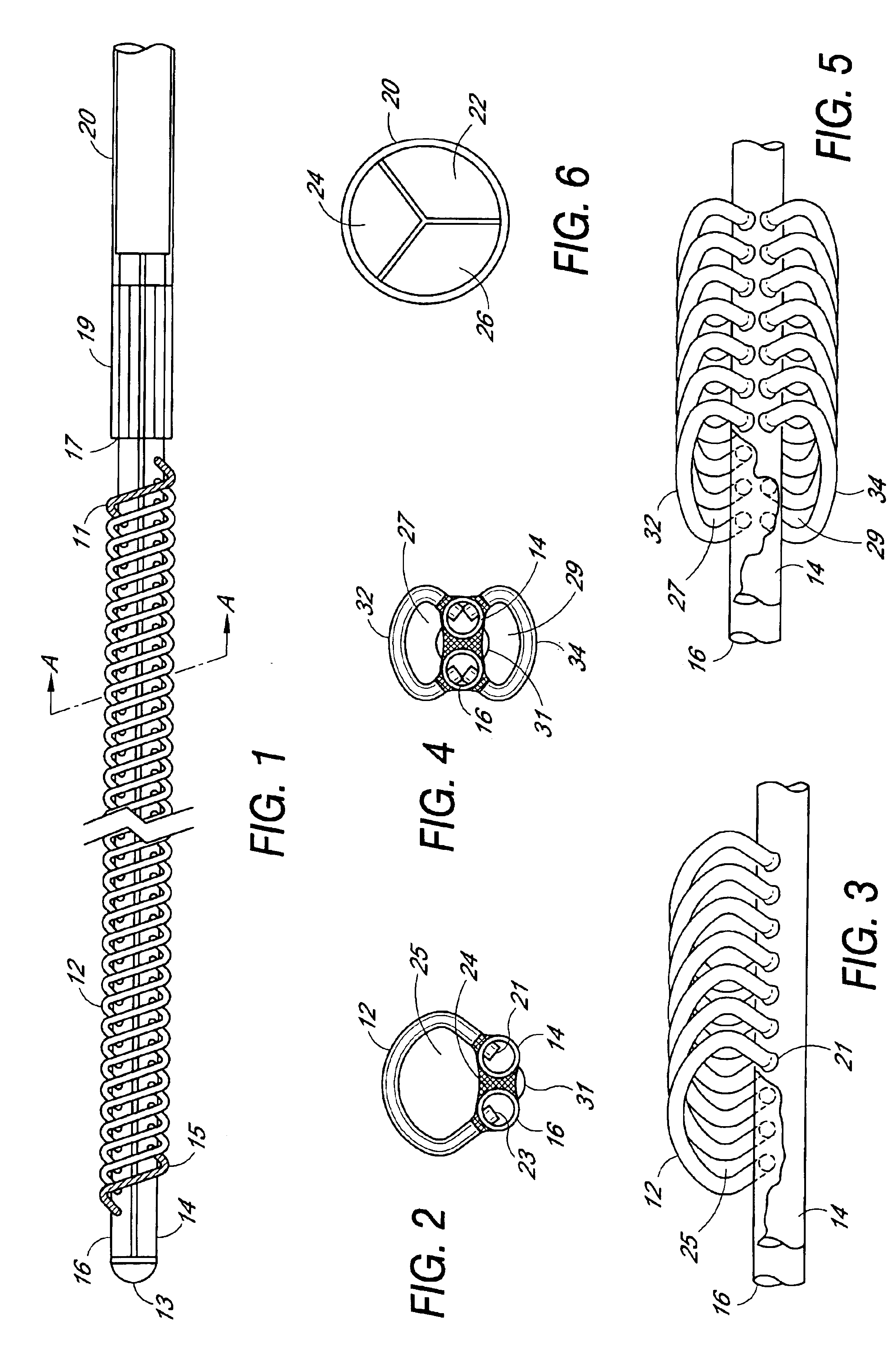
[0010]In the preferred embodiment illustrated in FIGS. 1-3, a pair of elongated hollow tubes are joined side-by-side lengthwise to form the core of the filter device. The two elongated hollow core tubes 14 and 16 terminate at a distal end with a distal end plug or cap 13 formed of a material that seals the open tube ends. The tubes and end cap may be made of any suitable biocompatible material, for example, medical grade extruded urethane tubes. Other biocompatible materials include synthetic rubbers, polycarbonate, polyethylene, polypropylene, nylon, etc. The elongated hollow tubes may be secured together using suitable bonding material 24, adhesive compositions, etc., for example, a UV curable adhesive applied along the length between the two tubes. The length and diameter of the filter device may be selected to accommodate the vessel or vein in which it is to be implanted. Accordingly, the diameter and length of the one or more elongated hollow tubes forming the central core of t...


PUM

PropertyMeasurementUnit
lengthaaaaaaaaaa
lengthaaaaaaaaaa
lengthaaaaaaaaaa

Abstract

A filter device for being implanted in a blood vessel for carrying out in-vivo plasma separation comprises one or more elongated hollow tubes and a plurality of elongated hollow microporous fibers, each fiber having a first and second end secured to one or more of the elongated hollow tubes with the interior lumen of each of the fibers communicating with the interior of the one or more of the hollow tubes, and wherein the fiber wall has a higher mass density zone adjacent to the outer wall surface and a lower mass density zone adjacent to the inner wall surface.

Description

BACKGROUND OF THE INVENTION[0001]In U.S. patent application Ser. No. 09 / 549,131 filed Apr. 13, 2000, (TRANSVI.007A) entitled “Specialized Hollow Fiber Membranes for In-Vivo Plasmapheresis and Ultrafiltration,” there are disclosed elongated hollow microporous fibers having an asymmetrical fiber wall characterized by having a lower mass density adjacent to the inner wall surface extending along the interior lumen of the fiber and a higher mass density adjacent to the outer wall surface. Such a fiber wall morphology and pore structure provide unique characteristics necessary for separating blood plasma and / or plasma water in-vivo where continuous extraction of cell-free plasma or ultrafiltered plasma water and its associated toxins is carried out within the blood vessel of a patient or animal. Conventional hollow fibers or filter membranes such as those used in dialysate filter devices are unable to successfully perform in-vivo, intravascular plasma separation, becoming clogged within ...

Claims


Application Information

Patent Timeline
Patent Type & Authority Patents(United States)
IPC IPC(8): A61M1/34A61M1/16B01D63/02
CPCA61M1/1678A61M1/3472A61M1/3496B01D63/02A61M1/3486A61M1/3431A61M1/3448A61M1/3479B01D63/024A61M1/34B01D2313/10A61M1/16A61M2205/50A61M1/3403A61M1/341
Inventor GORSUCH, REYNOLDS G.PETERS, HAROLD W.HANDLEY, JR., HAROLD H.
Owner TRANSVIVO
Why Eureka
Try Eureka