Capacitively coupled plasma reactor with uniform radial distribution of plasma

a plasma reactor and capacitively coupled technology, applied in the field of capacitively coupled plasma reactors with uniform radial distribution of plasma, can solve the problems of non-uniform plasma ion density distribution at the wafer or workpiece surface, non-uniform radial distribution of impedance, etc., and achieve the effect of enhancing plasma ion density uniformity

Inactive Publication Date: 2005-05-31
APPLIED MATERIALS INC
View PDF92 Cites 218 Cited by
  • Summary
  • Abstract
  • Description
  • Claims
  • Application Information

AI Technical Summary

Benefits of technology

[0005]A plasma reactor for processing a semiconductor wafer includes a side wall and an overhead ceiling defining a chamber, a workpiece support cathode within the chamber having a working surface facing the ceiling for supporting a semiconductor workpiece and a conductive mesh beneath the working surface for electrostatically chucking the wafer, process gas inlets for introducing a process gas into the chamber and an RF bias power generator having a bias power frequency. There is a bias power feed point

Problems solved by technology

The electrical field produced by the bias power tends to be nonuniform, which also leads to a non-uniform plasma ion density distribution at the wafer or workpiece surface.
In particular, one cause arises from the presence of a center conductor extending vertically upward through the workpiece support.
First, the center conductor affects the unifor

Method used


Image

  • Capacitively coupled plasma reactor with uniform radial distribution of plasma
  • Capacitively coupled plasma reactor with uniform radial distribution of plasma
  • Capacitively coupled plasma reactor with uniform radial distribution of plasma

Examples


Embodiment Construction

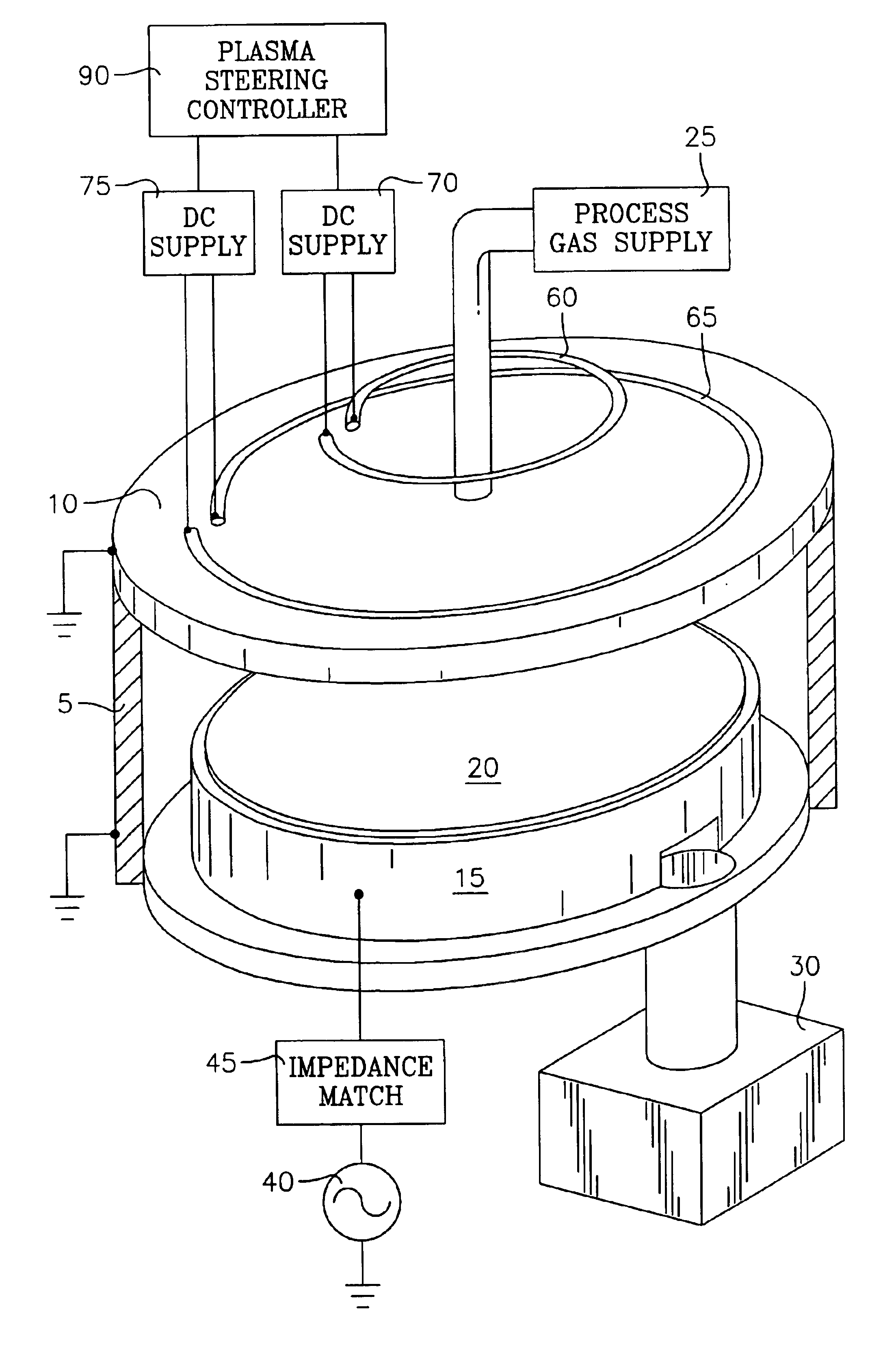
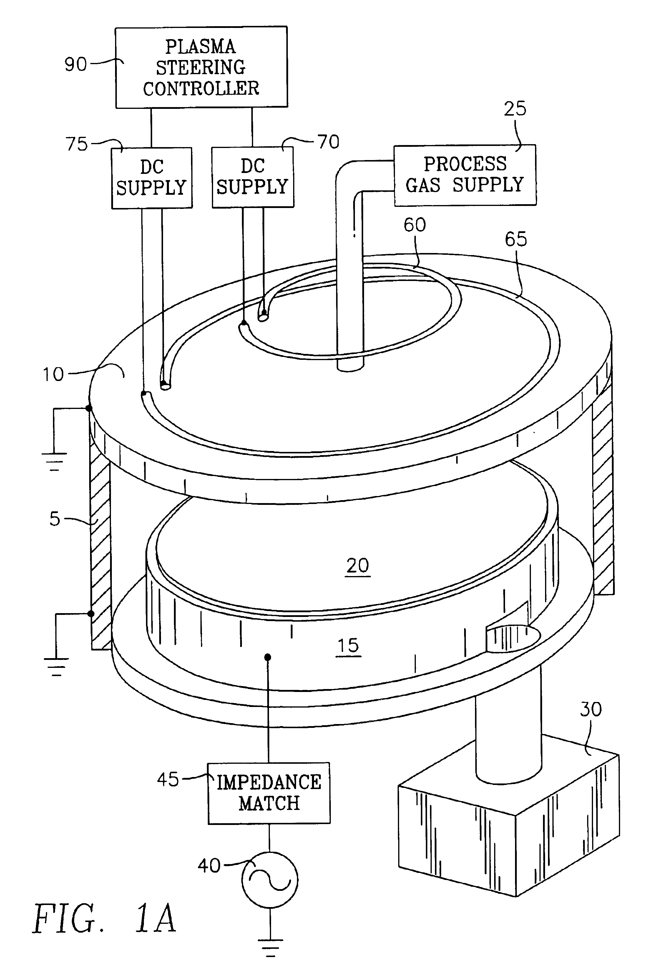
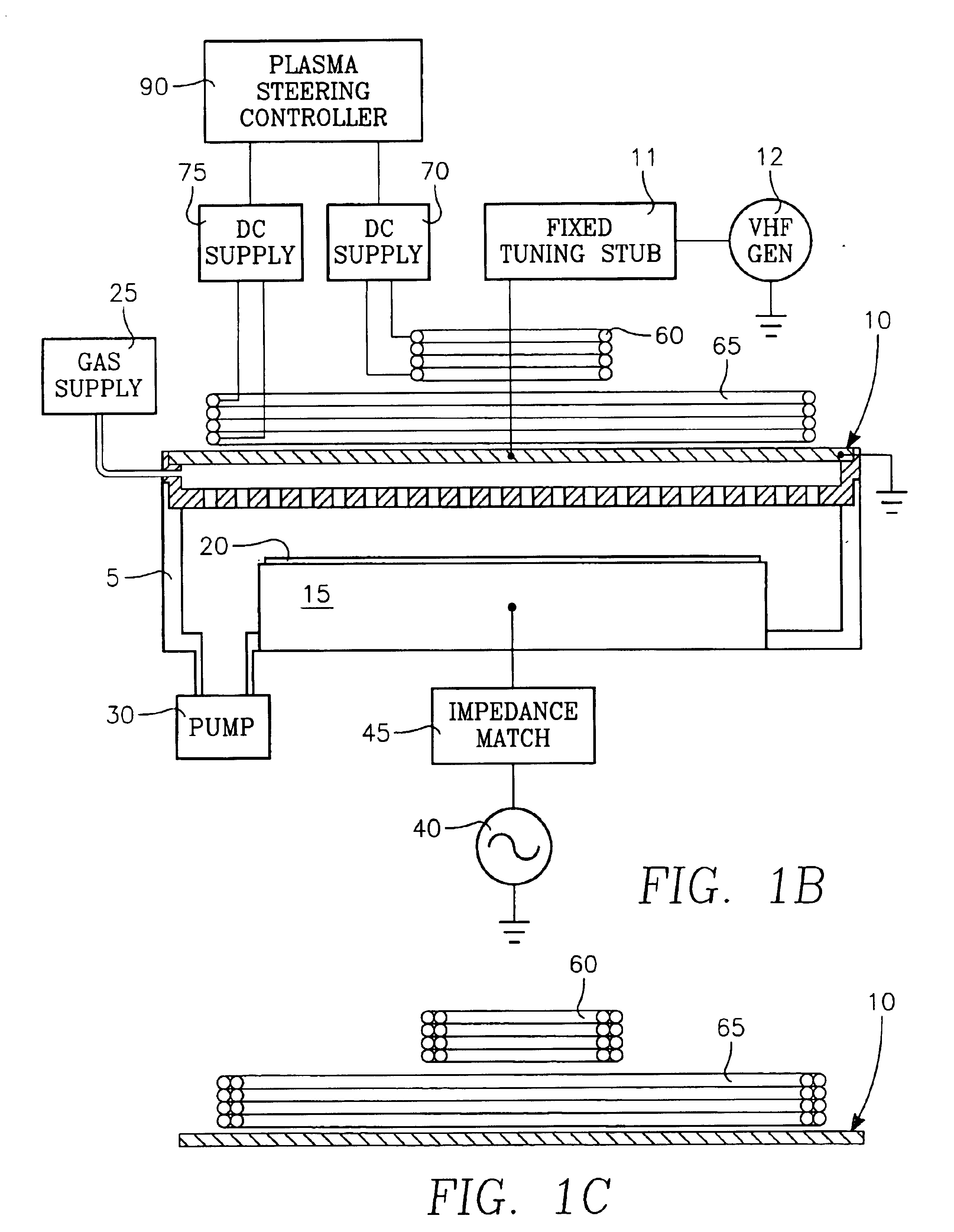
[0062]The plasma ion density distribution exhibited by a particular plasma reactor is a function of chamber pressure, gas mixture and diffusion, and source power radiation pattern. In the present invention, this distribution is magnetically altered to approximate a selected or ideal distribution that has been predetermined to improve process uniformity. The magnetically altered or corrected plasma ion density distribution is such that process uniformity across the surface of the wafer or workpiece is improved. For this purpose, the magnetically corrected plasma distribution may be non-uniform or it may be uniform, depending upon the needs determined by the user. We have discovered that the efficiency with which an average magnetic field strength exerts pressure on a plasma to change its distribution to a desired one can be improved. This surprising result can be achieved in accordance with this discovery by increasing the radial component of the gradient of the magnetic field. The r...


PUM

PropertyMeasurementUnit
Electrical resistanceaaaaaaaaaa
Lengthaaaaaaaaaa
Thicknessaaaaaaaaaa

Abstract

A plasma reactor for processing a semiconductor wafer includes a side wall and an overhead ceiling defining a chamber, a workpiece support cathode within the chamber having a working surface facing the ceiling for supporting a semiconductor workpiece, process gas inlets for introducing a process gas into the chamber and an RF bias power generator having a bias power frequency. There is a bias power feed point at the working surface and an RF conductor is connected between the RF bias power generator and the bias power feed point at the working surface. A dielectric sleeve surrounds a portion of the RF conductor, the sleeve having an axial length along the RF conductor, a dielectric constant and an axial location along the RF conductor, the length, dielectric constant and location of the sleeve being such that the sleeve provides a reactance that enhances plasma ion density uniformity over the working surface. In accordance with a further aspect, the reactor can include an annular RF coupling ring having an inner diameter corresponding generally to a periphery of the workpiece, the RF coupling ring extending a sufficient portion of a distance between the working surface and the overhead electrode to enhance plasma ion density near a periphery of the workpiece.

Description

CROSS-REFERENCE TO RELATED APPLICATIONS[0001]This application is a continuation in part of U.S. patent application Ser. No. 10 / 192,271 filed Jul. 9, 2002, now U.S. Pat. No. 6,853,141, entitled CAPACITIVELY COUPLED PLASMA REACTOR WITH MAGNETIC CONTROL By Daniel Hoffman et al.[0002]This application also contains subject matter related to the following applications: U.S. patent application Ser. No. 09 / 527,342 filed Mar. 17, 2000 entitled PLASMA RECTOR WITH OVERHEAD RF ELECTRODE TUNED TO THE PLASMA By Daniel Hoffman et al.; U.S. patent application Ser. No. 10 / 007,367 filed Oct. 22, 2001 entitled MERIE PLASMA REACTOR WITH OVERHEAD RF ELECTRODE TUNED TO THE PLASMA WITH ARCING SUPPRESSION By Daniel Hoffman et al., which is a continuation-in-part of U.S. patent application Ser. No. 09 / 527,342 filed Mar. 17, 2000; and U.S. patent application Ser. No. 10 / 028,922 filed Dec. 19, 2001 entitled PLASMA REACTOR WITH OVERHEAD RF ELECTRODE TUNED TO THE PLASMA WITH ARCING SUPPRESSION By Daniel Hoffman...

Claims


Application Information

Patent Timeline
IPC IPC(8): H01J37/32
CPCH01J37/32082H01J37/32091H01J37/3266H01J37/32623H01J37/3244H01J37/32H01J7/24
Inventor YANG, JANG GYOOHOFFMAN, DANIEL J.CARDUCCI, JAMES D.BUCHBERGER, JR., DOUGLAS A.HAGEN, ROBERT B.HAGEN, MELISSAMILLER, MATTHEW L.CHIANG, KANG-LIEDELGADINO, GERARDO A.
Owner APPLIED MATERIALS INC
Why Eureka
Try Eureka