Optical transmission system and terminal device applicable to the system

a technology of optical transmission system and terminal device, applied in multiplex communication, semiconductor laser, instruments, etc., can solve problems such as difficulty in flexible expansion of network, and achieve the effect of improving the extensibility of network

Inactive Publication Date: 2005-05-31
FUJITSU LTD
View PDF13 Cites 5 Cited by
  • Summary
  • Abstract
  • Description
  • Claims
  • Application Information

AI Technical Summary

Benefits of technology

[0008]It is therefore an object of the present invention to provide an optical transmission system improved in the extensibility of a network.

Problems solved by technology

Further, in the case that there arises a requirement for expansion of a network, such as a requirement for relocation of a certain one of the ONUs from an original position to a far position or to a near position or a requirement for increase in the number of subscribers, it is required that the transmitting power of each ONU reaching the OLT falls within a receivable level range of the OLT, causing a difficulty of flexible expansion of the network.

Method used


Image

  • Optical transmission system and terminal device applicable to the system
  • Optical transmission system and terminal device applicable to the system
  • Optical transmission system and terminal device applicable to the system

Examples


Embodiment Construction

[0031]Some preferred embodiments of the present invention will now be described in detail with reference to the attached drawings. Throughout the drawings, the same reference numerals denote like or corresponding parts.

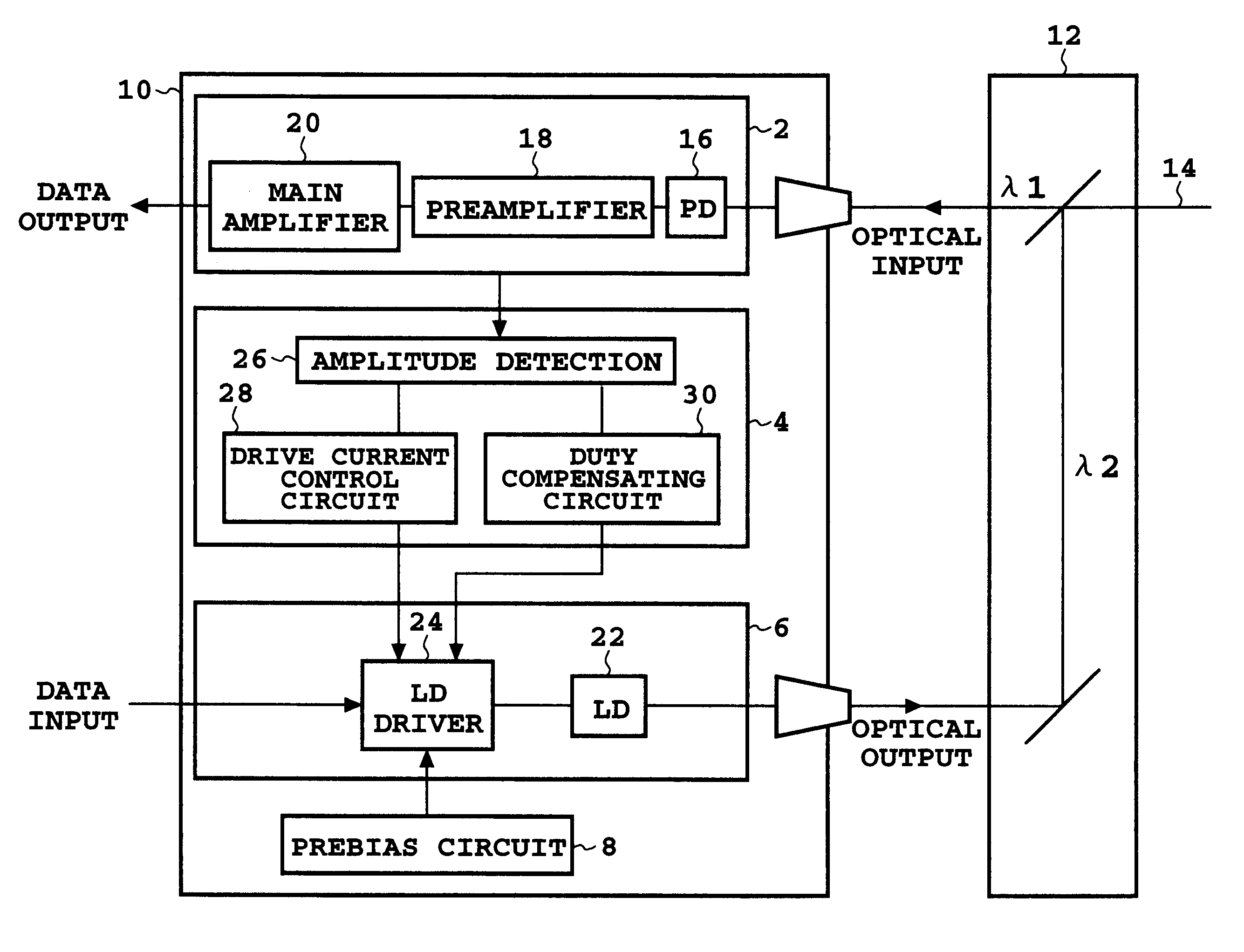
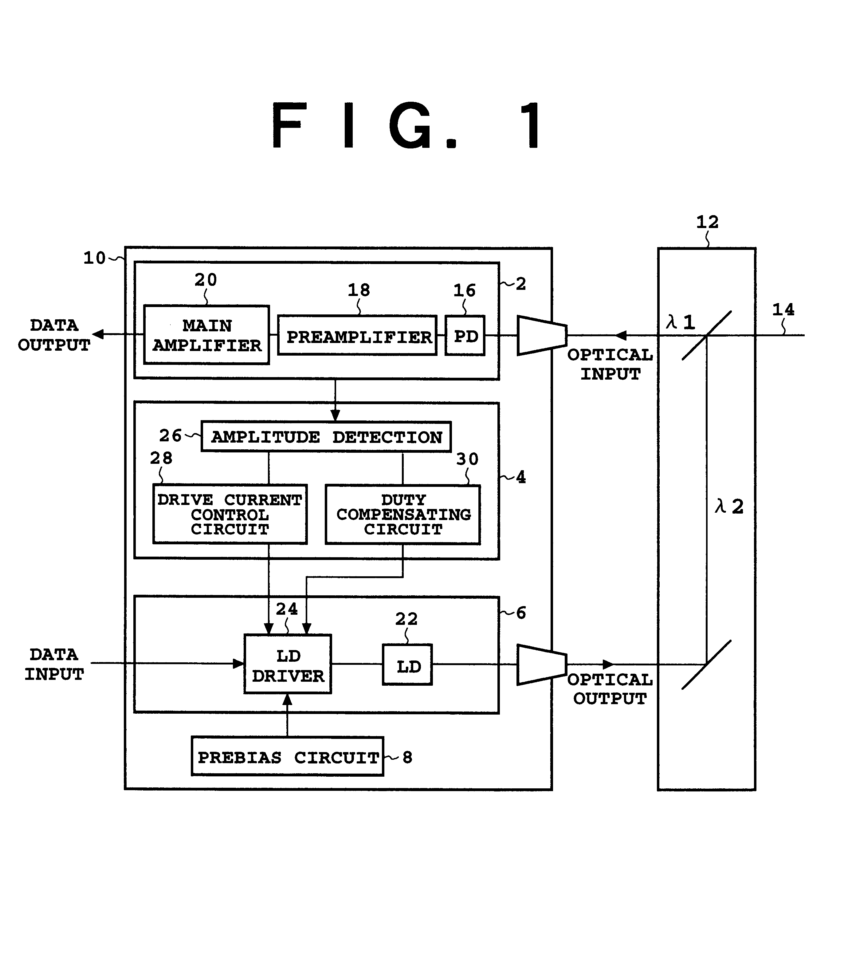
[0032]FIG. 1 is a block diagram showing a preferred embodiment of the terminal device according to the present invention. This device may be used as each ONU in an ATM-PON system. This terminal device includes a main circuit 10 and a WDM (wavelength division multiplexing) coupler 12 optically connected to the main circuit 10. The main circuit 10 includes a receiving section 2 for receiving an optical signal having a wavelength λ1 (e.g., 1.5 μm), a current control circuit 4, a transmitting section 6 for transmitting an optical signal having a wavelength λ2 (e.g., 1.3 μm), and a prebias circuit 8. The WDM coupler 12 couples the optical input having the wavelength λ1 relating to the receiving section 2 and the optical output having the wavelength λ2 relating to the trans...


PUM


Abstract

Disclosed herein is a terminal device including a photodetector, amplitude detecting circuit, light source, drive circuit, and control circuit. The photodetector receives a first optical signal. The amplitude detecting circuit detects the amplitude of an output from the photodetector. The drive circuit supplies a drive current to the light source so that the light source outputs a second optical signal. The control circuit decreases and increases the drive current according to an increase and decrease in the amplitude detected by the amplitude detecting circuit, respectively. In the case that this terminal device is used with another terminal device to construct a network, the dynamic range of the other terminal device can be reduced. Accordingly, the use of this terminal device can improve the extensibility of the network.

Description

[0001]This application is a continuation application, filed under 35 U.S.C. §111(a), of International Application PCT / JP99 / 04400, filed Aug. 13, 1999, it being further noted that priority is based upon International Patent Application PCT / JP99 / 4400, filed Aug. 13, 1999.BACKGROUND OF THE INVENTION[0002]1. Field of the Invention[0003]The present invention relates to an optical transmission system suitable for bidirectional transmission, and also to a terminal device applicable to this system.[0004]2. Description of the Related Art[0005]The international standard specifications of an ATM-PON (Asynchronous Transfer Mode-Passive Optical Network) system are defined in ITU-T: G983.1. This system includes a plurality of ONUs (Optical Network Units) as subscriber terminals, an OLT (Optical Line Terminal) as an office terminal device, and an optical star coupler for connecting the ONUs to the OLT so that bidirectional transmission is allowed between each ONU and the OLT.[0006]In general, the ...

Claims


Application Information

Patent Timeline
Patent Type & Authority Patents(United States)
IPC IPC(8): H04B10/155H04B10/152H04B10/207H01S5/06H01S5/00H04B10/25H04B10/07H04B10/2507H04B10/272
CPCH04B10/152H04B10/2589
Inventor YAMASHITA, SHINJIMORI, KAZUYUKIAKASHI, TAMOTSU
Owner FUJITSU LTD
Why Eureka
Try Eureka