System and method for monitoring power source longevity of an implantable medical device

Active Publication Date: 2005-05-31
MEDTRONIC INC
View PDF73 Cites 76 Cited by
  • Summary
  • Abstract
  • Description
  • Claims
  • Application Information

AI Technical Summary

Benefits of technology

[0016]These two techniques can be combined, however, to produce a power source longevity monitor having improved accuracy across the entire useful life of the power source. Using the technique of energy counting earlier in the useful life of the

Problems solved by technology

It is recognized, however, that the estimate of the amount of energy used by the implantable therapeutic delivery device is only an estimate and is not usually an exact measure.
Typically, the measurement or estimate of the amount of energy is only a certain percentage accur

Method used


Image

  • System and method for monitoring power source longevity of an implantable medical device
  • System and method for monitoring power source longevity of an implantable medical device
  • System and method for monitoring power source longevity of an implantable medical device

Examples


Embodiment Construction

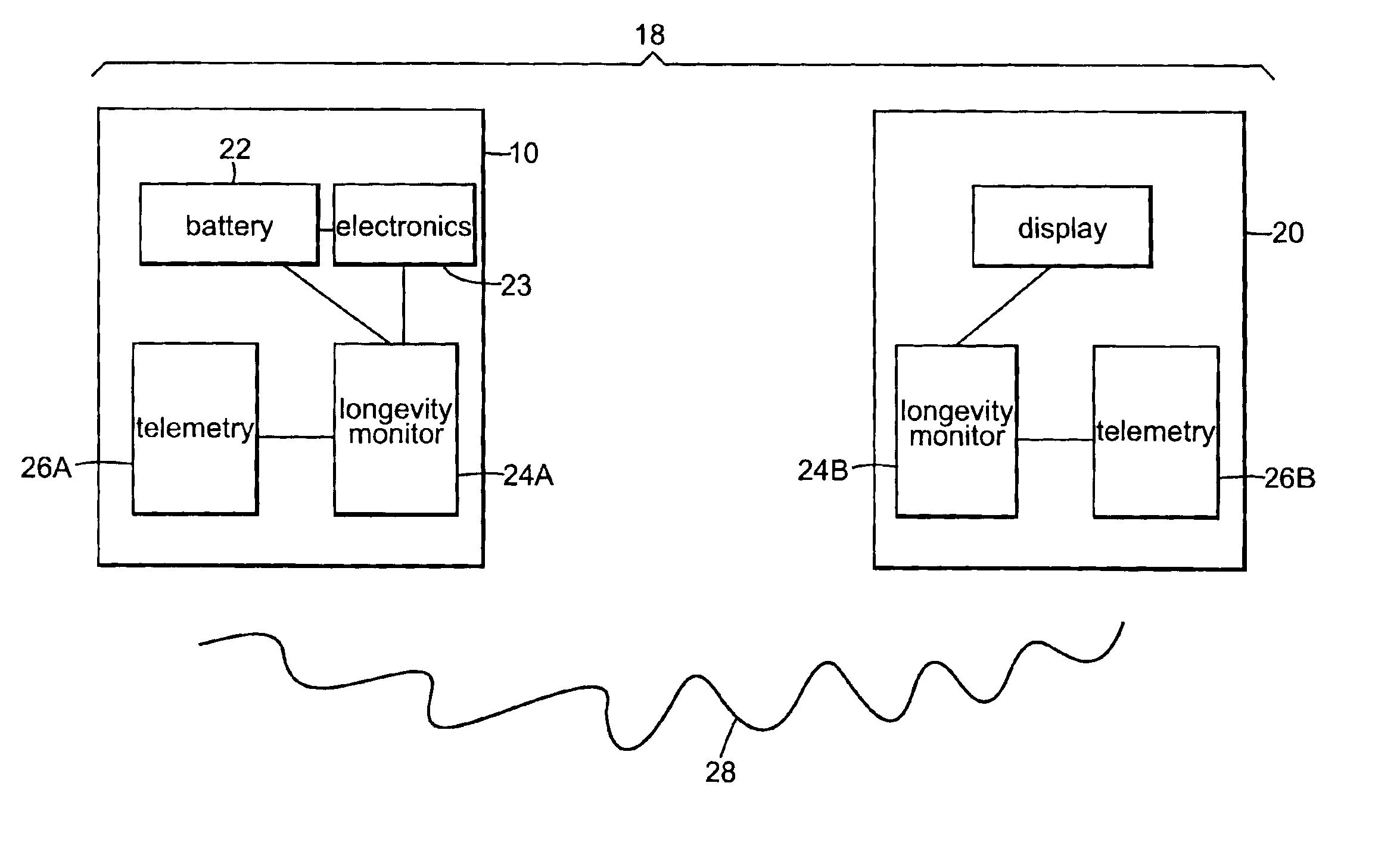
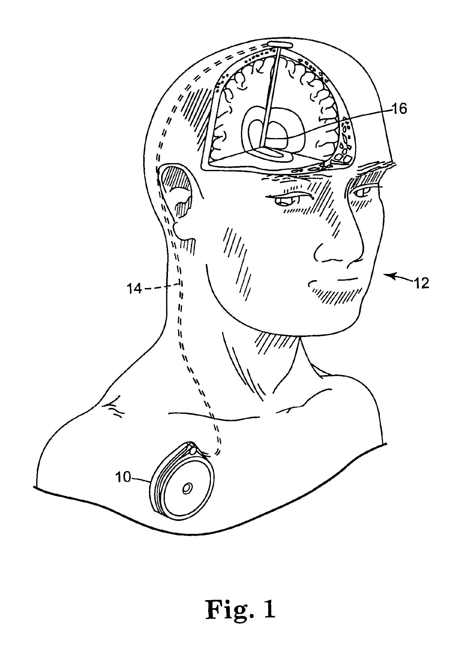
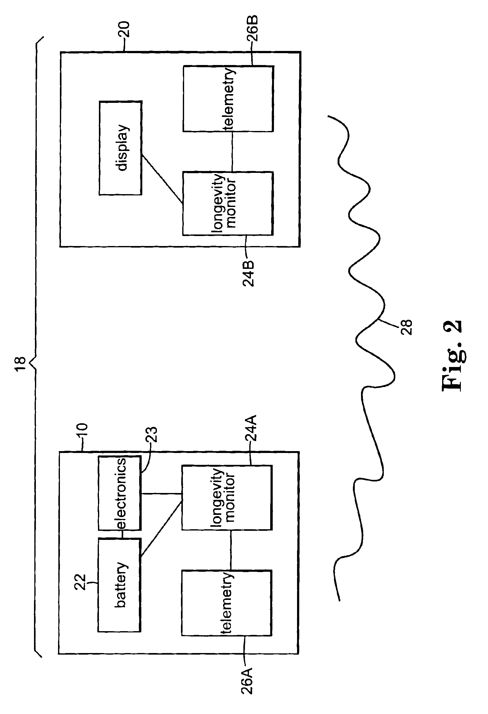
[0036]FIG. 1 shows implantable therapeutic delivery device 10, for example, a drug pump, implanted in patient 12. The implantable therapeutic delivery device 10 is typically implanted by a surgeon in a sterile surgical procedure performed under local, regional, or general anesthesia. Before implanting the therapeutic delivery device 10, a catheter 14 is typically implanted with the distal end position at a desired therapeutic delivery site 16 and the proximal end tunneled under the skin to the location where the therapeutic delivery device 10 is to be implanted. Implantable therapeutic delivery device 10 is generally implanted subcutaneous about 2.5 centimeter (1.0 inch) beneath the skin where there is sufficient tissue to support the implanted system. Once therapeutic delivery device 10 is implanted into the patient 12, the incision can be sutured closed and therapeutic delivery device 10 can begin operation.

[0037]Therapeutic substance delivery device 10 operates to infuse a therap...


PUM


Abstract

Power source longevity monitor for an implantable medical device. An energy counter counts the amount of energy used by the implantable medical device. An energy converter converts the energy used into an estimate of remaining power source longevity and generating an energy longevity estimate. A voltage monitor monitors the voltage of the power source. A voltage converter converts the voltage monitored by the voltage monitor into an estimate of remaining longevity of the power source and generating a voltage longevity estimate. A calculator is operatively coupled to the energy converter and to the voltage converter and predicts the power source longevity using the energy longevity estimate early in the useful life of the power source and using the voltage longevity estimate later in the useful life of the power source.

Description

FIELD OF THE INVENTION[0001]The present invention relates generally to power source monitors and, more particularly, to power source monitors for implantable medical devices having a power source having a voltage which declines over its useful life.BACKGROUND OF THE INVENTION[0002]The medical device industry produces a wide variety of electronic and mechanical devices for treating patient medical conditions. Depending upon the medical condition, medical devices can be surgically implanted or connected externally to the patient receiving treatment. Clinicians use medical devices alone or in combination with therapeutic substance therapies and surgery to treat patient medical conditions. For some medical conditions, medical devices provide the best, and sometimes the only, therapy to restore an individual to a more healthful condition and a fuller life.[0003]One type of medical device is an implantable therapeutic substance infusion device. An implantable therapeutic substance infusio...

Claims


Application Information

Patent Timeline
IPC IPC(8): A61M5/142A61N1/362A61N1/37G01R31/36A61K9/22
CPCA61M5/14276G01R31/3606A61M2205/3523A61N1/3708G01R31/3648A61M2205/8206G01R31/382
Inventor ROGERS, CHARLES R.MERRITT, DONALD R.SCHMIDT, CRAIG L.JAIN, MUKUL
Owner MEDTRONIC INC
Why Eureka
Try Eureka