Tension measuring device for mooring line

a technology a measuring device, which is applied in the direction of mooring line measurement, force/torque/work measurement apparatus, instruments, etc., can solve the problems of a mooring line bursting to a degree, a continuous rupturing of other lines, and a surge in the tension of the lin

Inactive Publication Date: 2005-06-07
CHEUNG MAXWELL C
View PDF17 Cites 41 Cited by
  • Summary
  • Abstract
  • Description
  • Claims
  • Application Information

AI Technical Summary

Benefits of technology

[0011]Embodiments according to the present invention measure tension in a line between a ship and a fixed object and at the same time, eliminate the necessity of pendent lines. The fixed object, among others, may be an anchor, a dock or other natural or artificial fixtures to which the line may be secured.

Problems solved by technology

Under turbulent wind and tidal conditions, the tension in a line may surge to a degree that may rupture the line.
Once a line is parted, remaining lines are subject to greater tension force in order to compensate for the lost tension in the disconnected line, which may lead to continuous rupturing of other lines.
Once all the lines are disconnected, the ship will drift away from its preferred location and cause significant injuries or property losses.
Such a device, however, may provide inaccurate reading when applied to soft synthetic lines where the cross section changes with level of tension.
It is also inaccurate when the mooring line wears out or flattens from prolonged use.
The difference is the error in the system.
Such a device is more complicated, expensive and the readings are indirect.
A continued measurement of the tension, however, was not practical in this system because vibrations need to be excited each time before the tension in the line can be measured.
Another problem in this system was that the vibration in the line might be influenced by changes in the unit weight of the line, possibly caused by rain, snow or other matters that may accumulate on the line.

Method used


Image

  • Tension measuring device for mooring line
  • Tension measuring device for mooring line
  • Tension measuring device for mooring line

Examples


first embodiment

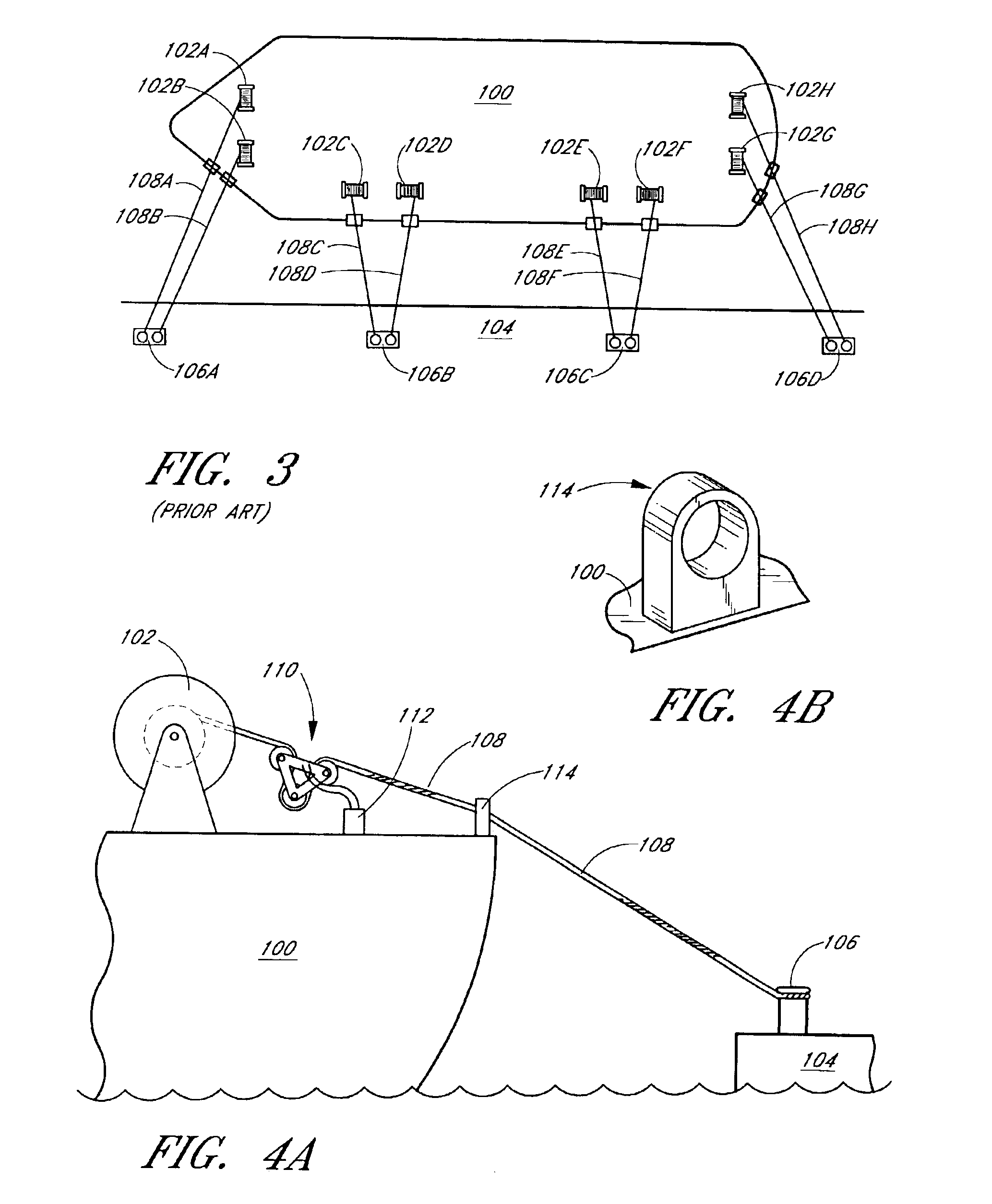
[0038]Referring to FIG. 5, the tension measuring device 110 comprises a first pulley 210, a second pulley 220 and a third pulley 230. The pulleys 210, 220, 230 are secured to triangular frames 250, 350 by means of shafts 242, 244, 246 by any suitable method. The front frame 250 comprises a first arm 252, a second arm 254 and a third arm 256. The first pulley 210 is mounted at the apex formed by the arms 252 and 256. The second pulley 220 is mounted at the apex formed by the arms 254 and 256. The third pulley 230 is mounted at the apex formed by the arms 252 and 254. The rear triangular frame 350 also comprises three arms securing the pulleys 210, 220, 230 in a same manner as described above. The mooring line 108 extends from the winch 102 of the ship 100, winds over the first pulley 210, winds below the third pulley 230, and winds over the second pulley 220 and through the chock 114 at the side of the ship before extending to a mooring post or hook 106 fixed onto the dock.

[0039]The ...

second embodiment

[0058]Various modifications can be made to the One modification may involve replacing the left rods 522, 622 or right rods 524, 624 with compressive springs and replacing the tension springs 530, 630 with a rigid rod between the shafts 540, 542. In such a modification, the extensometer should be placed along the compressive springs to measure the displacement of the compressive spring. Using compressive springs instead of tension springs may have the benefit of built-in safety feature because the compression springs will not compress beyond a certain limit.

[0059]Another modification may involve changing the angle α. The angle α in the second embodiment need not be 90 degrees and can be increased or decreased. Alternately, other modifications similar to the ones in the first embodiment can be made.

third embodiment

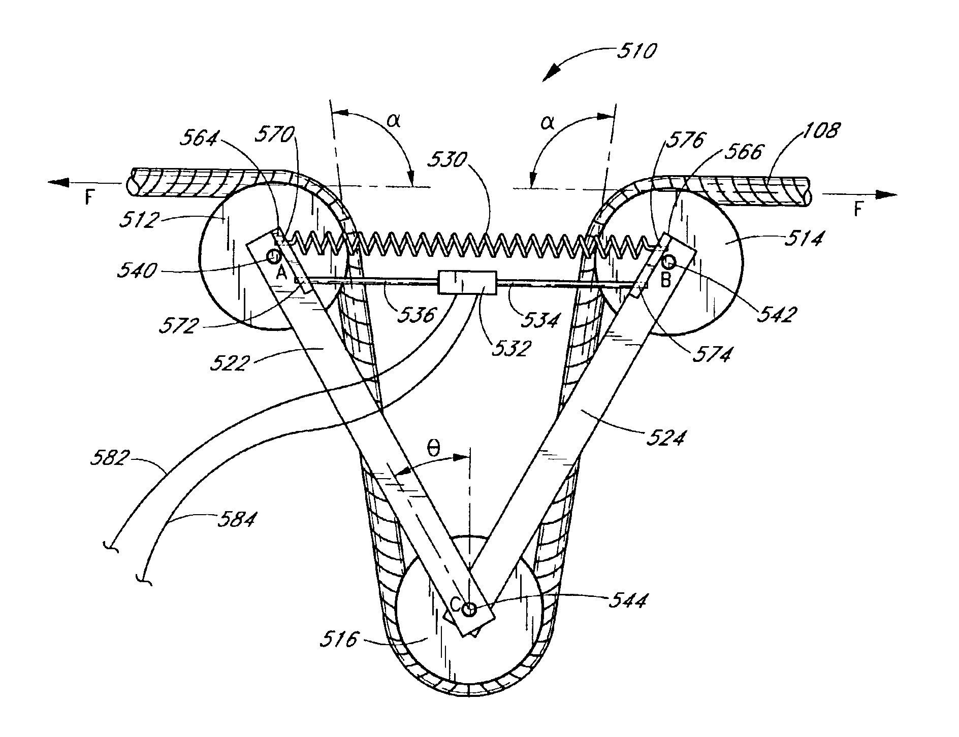
[0060]FIGS. 11-14 show a tension measuring device 700 wherein a compressive spring 724 is installed between first and second pulleys 712, 714 secured to a crossbeam 750 by shafts 734, 736. A third pulley 716 is secured to a bracket 720 by a shaft 738. A center rod 752 positioned within the spring 724 extends between the bracket 720 and the crossbeam 750. An extensometer 754 is connected to an end of the center rod 752. The other end of the center rod 752 is secured to a center part of the crossbeam 750 by a nut 728. Any other securing means, such as adhesives or locking pins can be used in place of the nut 728. A first receiving plate 730 is placed between the bracket 720 and the compression spring 724. A second receiving plate 732 is placed between the crossbeam 750 and the compression spring 724.

[0061]Letters A, B, C in FIG. 11 denote centers of the shafts 734, 736, 738 and pulleys 712, 714, 716. The centers A and B of the shafts 734, 736 are located at a same vertical level above...


PUM

PropertyMeasurementUnit
angleaaaaaaaaaa
buffering tensionaaaaaaaaaa
tensionaaaaaaaaaa

Abstract

A device for measuring tension in a line for mooring a ship to a dock or an anchor. The device includes three pulleys secured to rigid frames or springs. Sensors are placed on rigid frames, springs or shafts for securing the pulleys. Portions of the mooring line extending from a center pulley to the other two pulleys are approximately perpendicular to portions of line extending from the two pulleys to a winch or a mooring post or hook. The springs between the pulleys may provide resilience in the mooring line which may obviate a need for a pendent line between the mooring line and the winch. The sensors communicate with a signal-processing unit which transmits amplified sensor signals to a monitor which is accessible to personnel aboard the ship. The monitor may display the tension in the mooring line in text or graphic formats.

Description

BACKGROUND OF THE INVENTION[0001]1. Field of the Invention[0002]The present invention relates to a tension measuring device associated with ship mooring systems, particularly to a tension measuring device mounted on a mooring line for securing a ship to a fixed object such as an anchor, a dock or other structures.[0003]2. Description of the Related Art[0004]Generally, a mooring line extends from a winch of a ship to a fixed object such as an anchor or a dock. In the course of mooring the ship, the mooring line is subject to tension that fluctuates according to the oscillating behavior of the ships and external force exerted by tides, current and winds. Under turbulent wind and tidal conditions, the tension in a line may surge to a degree that may rupture the line.[0005]Once a line is parted, remaining lines are subject to greater tension force in order to compensate for the lost tension in the disconnected line, which may lead to continuous rupturing of other lines. Once all the lin...

Claims


Application Information

Patent Timeline
Patent Type & Authority Patents(United States)
IPC IPC(8): G01L5/04G01L5/10
CPCG01L5/10G01L5/107G01L5/102
Inventor CHEUNG, MAXWELL C.
Owner CHEUNG MAXWELL C
Why Eureka
Try Eureka