Pneumatically operated active vibration damping device

a damping device and pneumatic operation technology, which is applied in the direction of shock absorbers, jet propulsion mountings, machine supports, etc., can solve the problems of deteriorating the isolating effect of the active vibration damping device with respect, and affecting the stability of the damping device. , to achieve the effect of high space utilization and simple construction

Inactive Publication Date: 2005-06-07
SUMITOMO RIKO CO LTD
View PDF30 Cites 18 Cited by
  • Summary
  • Abstract
  • Description
  • Claims
  • Application Information

AI Technical Summary

Benefits of technology

[0013]It is therefore an object of this invention to provide a pneumatically operated active vibration damping device which is novel in construction, and which is capable of exhibiting an excellent active damping effect with respect to vibrations of a plurality of frequency ranges or over a wide frequency range on the basis of an effective control of a fluid pressure within a pressure receiving chamber owing to an oscillation of an elastic oscillating plate, while assuring a sufficient damping effect with respect to low frequency vibrations on the basis of flows or resonance of the fluid which is forced to flow through a first orifice passage.

Problems solved by technology

However, the large spring stiffness of the oscillating elastic plate may deteriorate oscillation efficiency of the oscillating elastic plate caused by the periodic air pressure change induced in the oscillating air chamber.
This makes it difficult to control the fluid pressure in the pressure-receiving chamber with efficiency, leading to deterioration of active vibration isolating effect of the damping device with respect to the high frequency vibrations.
The extensive studies on the proposed active vibration damping device, which were made by the present inventors have revealed that the efficient transmission of the fluid pressure change between the primary and auxiliary fluid chamber owing to the resonance of the fluid flowing through the second orifice passage is just effective with respect to vibrations in a very limited frequency band, and a resistance to flow of the fluid through the second orifice passage tents to be increased when frequencies of the vibrations become higher than the limited frequency band to which the second orifice passage is tuned, resulting in significant deterioration of the pressure transmitting efficiency between the primary and auxiliary fluid chambers upon application of the higher frequency vibrations.
Accordingly, the proposed active vibration-damping device still suffers from an inherent problem of deterioration of its vibration damping or isolating effect with respect to the high frequency vibrations.
Due to the above-described increase of the resistance to flow of the fluid through the second orifice passage, the fluid pressure change in the pressure receiving chamber upon application of the high frequency vibrations is never absorbed by the volumetric change of the auxiliary fluid chamber, as well as the equilibrium chamber, leading to a higher dynamic spring constant of the vibration damping device, resulting in deterioration of the passive vibration damping effect of the vibration damping device.
That is, the proposed pneumatically oscillated active vibration damping device disclosed in JP-A-10-184770 is still insufficient to exhibit a sufficiently vibration damping effect with respect to vibrations over a wide frequency range, namely a low frequency range to which the first orifice passage is tuned, a high frequency range to which the second orifice passage is tuned, and a higher frequency range which is higher than the frequency range to which the second orifice passage is tuned.

Method used


Image

  • Pneumatically operated active vibration damping device
  • Pneumatically operated active vibration damping device
  • Pneumatically operated active vibration damping device

Examples


Embodiment Construction

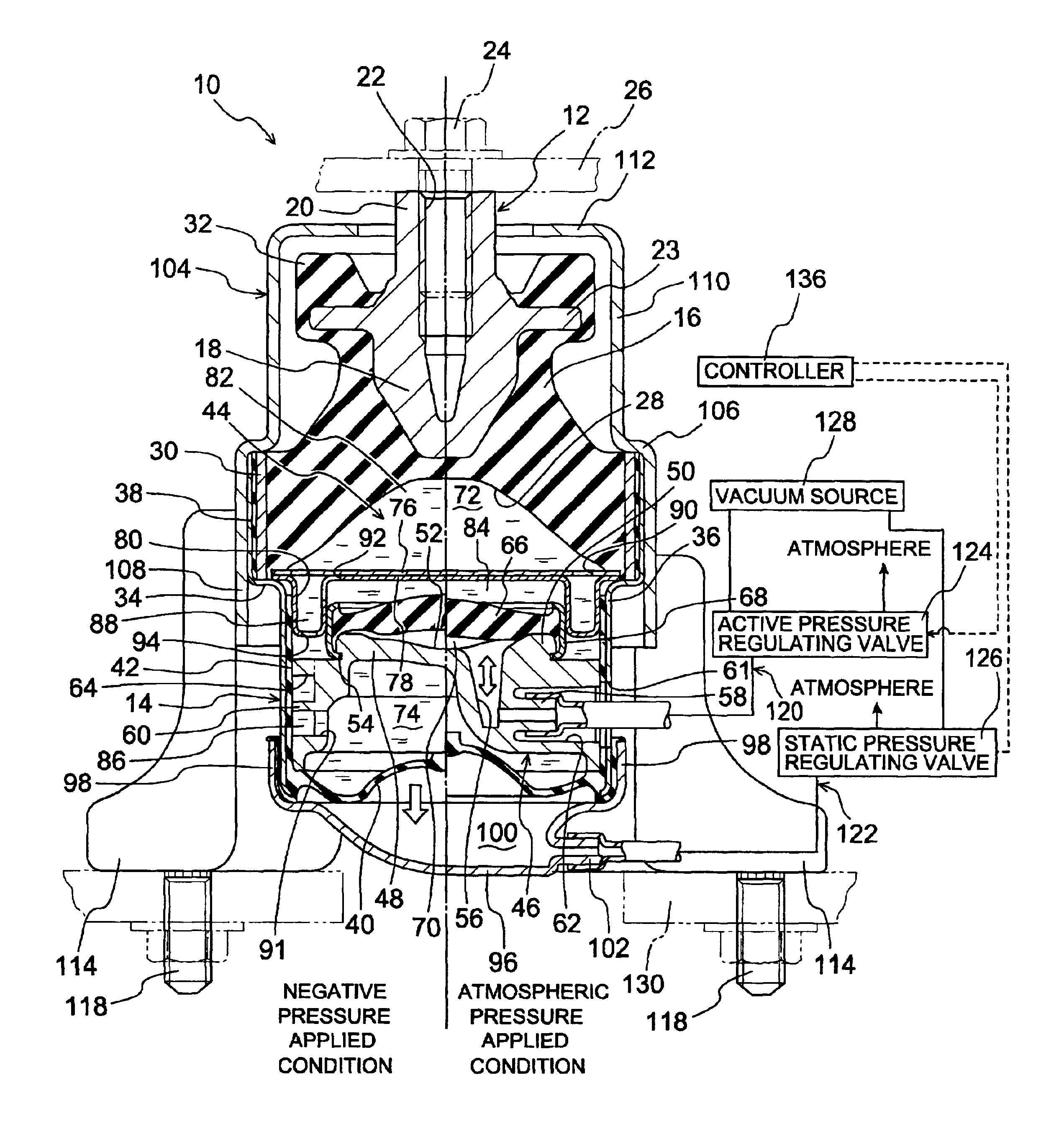
[0046]Referring first to FIG. 1, there is shown an engine mount 10 for an automotive vehicle, as one embodiment of a pneumatically operated active vibration-damping device of the present invention. This engine mount 10 includes a first mounting member 12 and a second mounting member 14 which are both made of metallic materials and which are disposed in mutually opposed and spaced-apart relationship with each other. These first and second mounting members 12, 14 are elastically connected to each other by an elastic body 16 made of a rubber material and fixed thereto upon vulcanization of the rubber material for forming the elastic body 16. The first and second mounting members 12, 14 are adapted to be attached to a power unit 26 (see FIG. 2) and a body 130 (see FIG. 2) of the motor vehicle, respectively, so that the power unit, which includes an engine, is mounted on the vehicle body in a vibration damping and / or isolating fashion. With this engine mount 10 installed on the vehicle a...


PUM


Abstract

Disclosed is a pneumatically operated active vibration damping device including an elastic oscillating plate partially define a pressure receiving chamber formed on one side thereof and an oscillating air chamber formed on the other side thereof, wherein the elastic oscillating plate is oscillated due to a periodic change of the air pressure generated in the oscillating air chamber so as to exhibit active vibration damping effect of the device, and wherein at least one of the pressure receiving chamber and the oscillating air chamber undergoes a static pressure change so as to change a spring stiffness of the elastic oscillating plate. Thus, the device is capable of changing its active vibration damping characteristics based on the oscillation of the elastic oscillating plate.

Description

INCORPORATED BY REFERENCE[0001]The disclosure of Japanese Patent Application NO. 2000-370401 filed on Dec. 5, 2000 including the specification, drawings and abstract is incorporated herein by reference in its entirety.BACKGROUND OF THE INVENTION[0002]1. Field of the Invention[0003]The present invention relates generally to an active vibration damping device interposed between two members of a vibration system for actively attenuating or reducing vibrations transmitted between the two members, more particularly to a pneumatically operated active vibration damping device capable of changing its vibration damping or isolating characteristics depending upon vibrations to be damped, by utilizing an air pressure change.[0004]2. Description of the Related Art[0005]A known example of the above type of pneumatically operated active vibration damping device is disclosed in JP-A-10-184769. The disclosed active vibration-damping device includes: a first and a second mounting member connectable ...

Claims


Application Information

Patent Timeline
Patent Type & AuthorityPatents(United States)
IPC IPC(8): F16F13/26F16F13/04B60K5/12F16F15/02
CPCF16F13/26
InventorMURAMATSU, ATSUSHIKATO, KAZUHIKOHATANO, MOTOHIRO
OwnerSUMITOMO RIKO CO LTD