This helps you quickly interpret patents by identifying the three key elements:
Problems solved by technology
Method used
Benefits of technology
Benefits of technology
[0008]In view of the above, the present invention may provide a power supply apparatus that reduces its own current consumption at the time of a light load, to thereby improve an overall power conversion efficiency thereof.
Problems solved by technology
However, since a charge pump DC / DC converter is designed taking in account of the maximum load for its operation, its own current consumption is the same even when a load condition changes.
Therefore, it does not waste the power at the time of a heavy load, but it is inconvenient that its capacity becomes excessive at the time of a light load such that the power is wasted, and the overall power conversion efficiency is lowered.
However, it is inconvenient that the overall power conversion efficiency is lowered because its own current consumption is large at the time of a light load.
Method used
Image
Click on the blue label to locate the original text in one second.
Reading with bidirectional positioning of images and text.
Examples
first embodiment
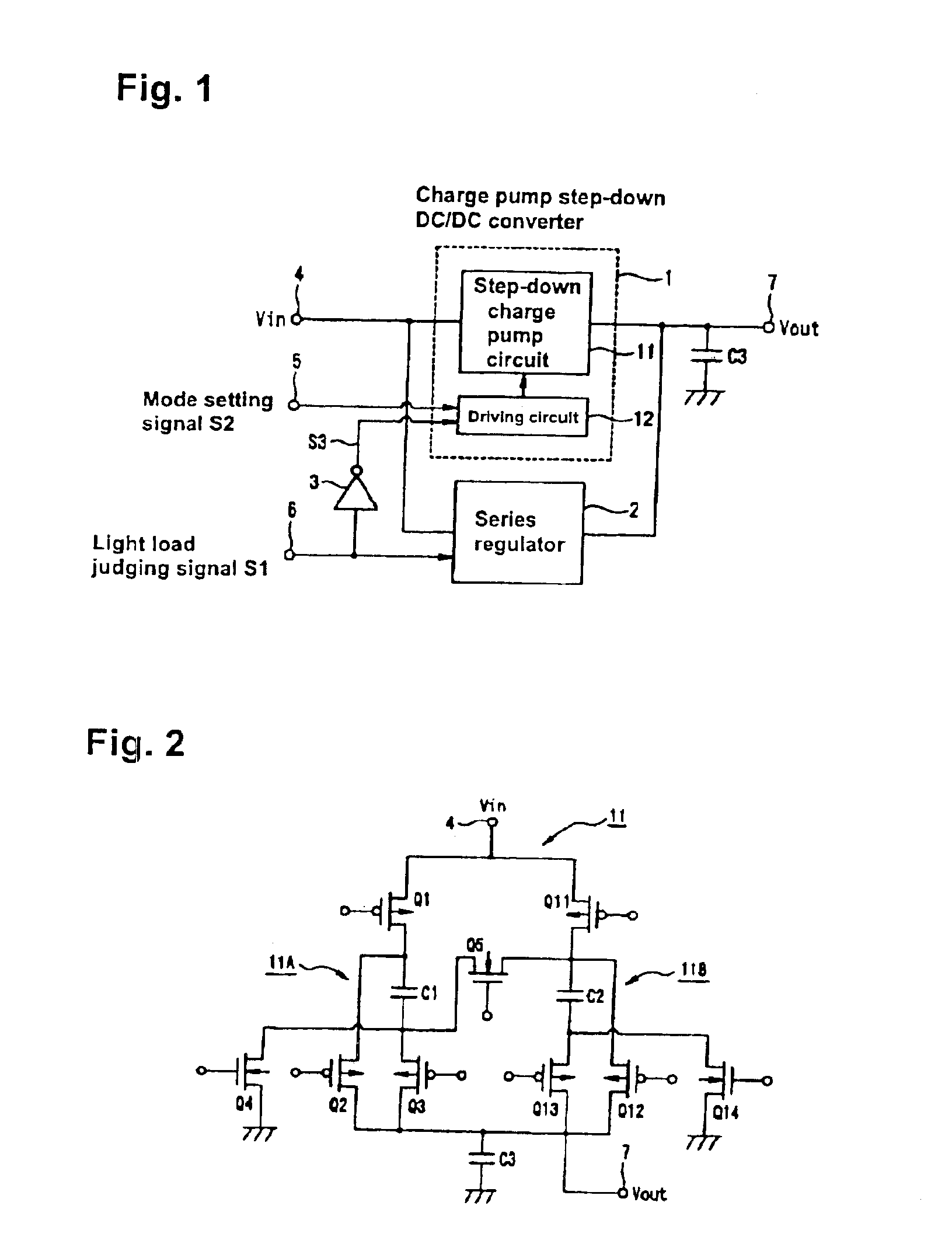
[0047]A power supply apparatus in accordance with the present invention is described below with reference to FIG. 1.
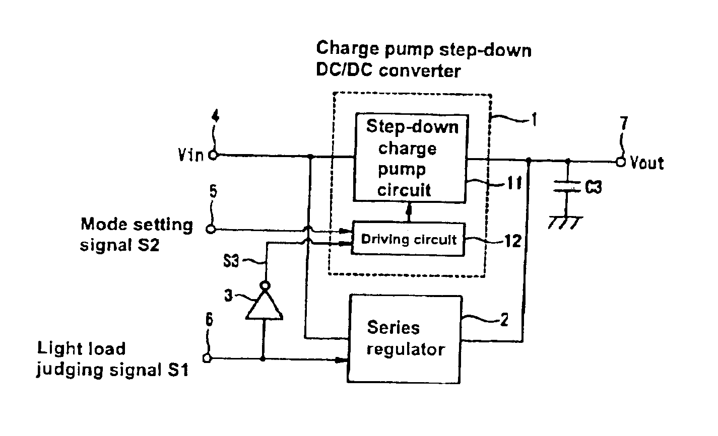
[0048]As shown in FIG. 1, the power supply apparatus in accordance with the first embodiment of the present invention is equipped with a charge pump step-down DC / DC converter 1 and a series regulator 2 connected in parallel between an input terminal 4 and an output terminal 7, The step-down DC / DC converter 1 and the series regulator 2 are selectively operated based on a light load judging signal S1, and an output voltage on the operating side is taken out from an output terminal 3.
[0049]The step-down DC / DC converter 1 uses charge and discharge of a capacitor to convert an input voltage Vin inputted into the input terminal 4 into a predetermined output voltage Vout, and is composed of a step-down charge pump circuit 11 and a driving circuit 12 that drives the step-down charge pump circuit 11.
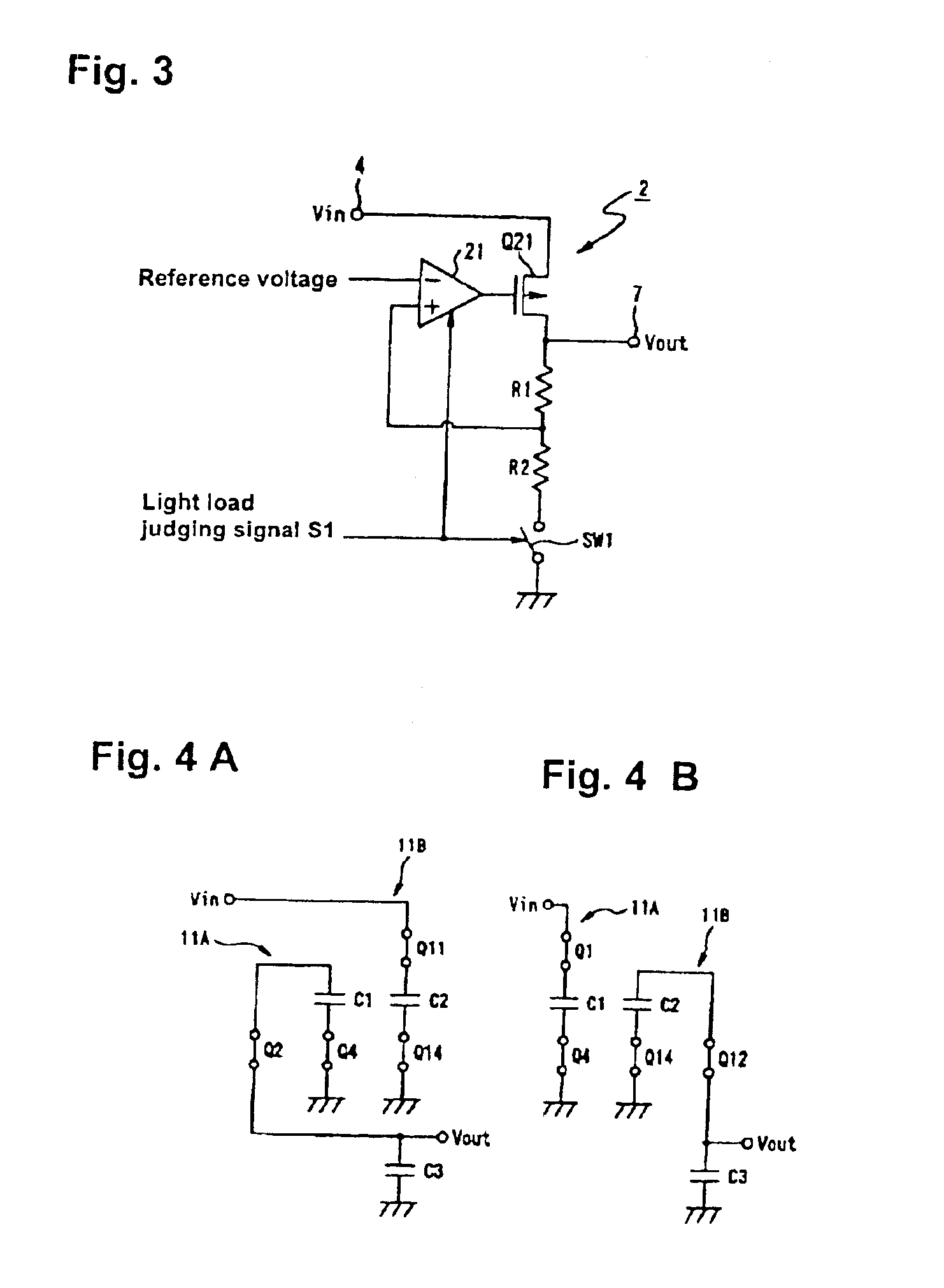
[0050]The step-down charge pump circuit 11 is formed from, for example, as show...
second embodiment
[0088]Next, a power supply apparatus in accordance with the present invention is described with reference to FIG. 6.
[0089]As shown in FIG. 6, the power supply apparatus in accordance with the second embodiment of the present invention is equipped with a step-down switching regulator 8 and a series regulator 2 connected in parallel between an input terminal 4 and an output terminal 7. The step-down switching regulator 8 and the series regulator 2 are selectively operated based on a light load judging signal S1, and an output voltage on an operation side thereof is taken out from an output terminal 3.
[0090]The series regulator 2 is the same as the series regulator 2 shown in FIG. 1 and FIG. 3.
[0091]The step-down switching regulator 8 switches an input voltage and converts the input voltage into a predetermined output voltage, and has a structure shown in FIG. 7, for example.
[0092]The step-down switching regulator 8 includes a MOS transistor Q31 and a coil L1 serially connected between...
third embodiment
[0114]A power supply apparatus constructed in accordance with the present invention will be described with reference to FIG. 8.
[0115]As shown in FIG. 8, the power supply apparatus comprises a charge pump step-down DC / DC converter 1 and a series regulator 2, the converter and regulator having different characteristics and being connected in parallel between an input terminal 4 and an output terminal 7. The step-down DC / DC converter and series regulator 1, 2 are selectively operated based on an operation command signal S11 inputted into a control terminal 44 and a load detection signal S12 from a load detecting circuit 42. The output voltage on the operation side is taken out from the output terminal 7.
[0116]A load (not shown) is connected to the power supply apparatus of the third embodiment. The load is desirably controlled by a microcomputer (processor) (not shown) through a predetermined program. On controlling the load, thus, the change of a load can be already known or predicted...
PUM
Abstract
A DC / DC converter and a series regulator are connected in parallel between an input terminal and an output terminal. At the time of a heavy load, the DC / DC converter is operated. Although the DC / DC converter has a large current consumption of its own, it has a high power conversion efficiency. Accordingly, since a load current increases at the time of a heavy load, it is effective to use the DC / DC converter whose power conversion efficiency is high, and its current consumption can be neglected since the load current is large. On the other hand, at the time of a light load, the series regulator is operated. Although the series regulator has a small current consumption of its own, it has a low power conversion efficiency. Accordingly, at the time of a light load, even when the series regulator is used, its low power conversion efficiency can be neglected because its current consumption is small. Accordingly, the current consumption of its own can be lowered at the time of a light load, and the power conversion efficiency as a whole can be improved when it is used both at a heavy load and a light load.
Description
CROSS REFERENCE TO RELATED APPLICATIONS[0001]This patent application is a division of U.S. patent Ser. No. 10 / 123,863 filed Apr. 16, 2002, which is a continuation-in-part application based on U.S. patent Ser. No. 10 / 057,308 filed on Jan. 25, 2001. All the contents of Japanese Patent Application No. 2001-20703 filed on Jan. 29, 2001 and Japanese Patent Application No. 2002-17652 filed on Jan. 25, 2002 are incorporated by reference.BACKGROUND OF THE INVENTION[0002]The present invention relates to a power supply apparatus that reduces its own current consumption at the time of a light load to thereby eliminate power wastage, to thereby improve an overall power conversion efficiency thereof.[0003]Conventionally, for example, charge pump DC / DC converters and switching regulators are known as power supply apparatuses.[0004]A charge pump DC / DC converter uses charge and discharge of a capacitor to convert an input voltage to a predetermined output voltage.[0005]A switching regulator switche...
Claims
Application Information
Patent Timeline
Application Date:The date an application was filed.
Publication Date:The date a patent or application was officially published.
First Publication Date:The earliest publication date of a patent with the same application number.
Issue Date:Publication date of the patent grant document.
PCT Entry Date:The Entry date of PCT National Phase.
Estimated Expiry Date:The statutory expiry date of a patent right according to the Patent Law, and it is the longest term of protection that the patent right can achieve without the termination of the patent right due to other reasons(Term extension factor has been taken into account ).
Invalid Date:Actual expiry date is based on effective date or publication date of legal transaction data of invalid patent.

