Engine control and catalyst monitoring with downstream exhaust gas sensors

a technology of catalyst monitoring and exhaust gas sensors, which is applied in the direction of electrical control, machine/engine, exhaust treatment electric control, etc., can solve the problems of complex engine control system, difficult to determine the operating conditions and dynamics of any catalyst (or portion thereof) further downstream, and achieve cost and weight saving

Inactive Publication Date: 2005-06-14
FORD GLOBAL TECH LLC
View PDF14 Cites 80 Cited by
  • Summary
  • Abstract
  • Description
  • Claims
  • Application Information

AI Technical Summary

Benefits of technology

[0013]The present invention provides a number of advantages. For example, the present invention provides a robust engine controller that adapts to changing catalyst dynamics on-line. The invention allows use of a relatively simple catalyst model that sufficiently captures the catalyst behavior to provide on-line calculation of the catalyst gain for real-time updates in the engine controller. The robust control and management of catalyst conversion efficiency afforded by the present invention may allow reduction of the catalyst volume with corresponding savings in cost and weight. Using multiple downstream exhaust gas sensors allows monitoring of catalyst conversion efficiency and corresponding adaptation of control for applications employing close-coupled / fast light-off catalysts.

Problems solved by technology

Robust management of catalyst conversion efficiency via fuel / air ratio control is complicated by the catalyst dynamics, which change with air flow rate, catalyst temperature, and catalyst age, for example.
Various engine and vehicle operating conditions, such as idling with a hot catalyst, also present challenges for the engine control system due to the extremely slow dynamics under these conditions.
However, even though the downstream exhaust gas sensor monitoring the fast light-off portion of the catalyst is appropriately tracking a desired set point, the operating conditions and dynamics of any catalyst (or portion thereof) positioned further downstream cannot be easily determined.

Method used


Image

  • Engine control and catalyst monitoring with downstream exhaust gas sensors
  • Engine control and catalyst monitoring with downstream exhaust gas sensors
  • Engine control and catalyst monitoring with downstream exhaust gas sensors

Examples


Embodiment Construction

)

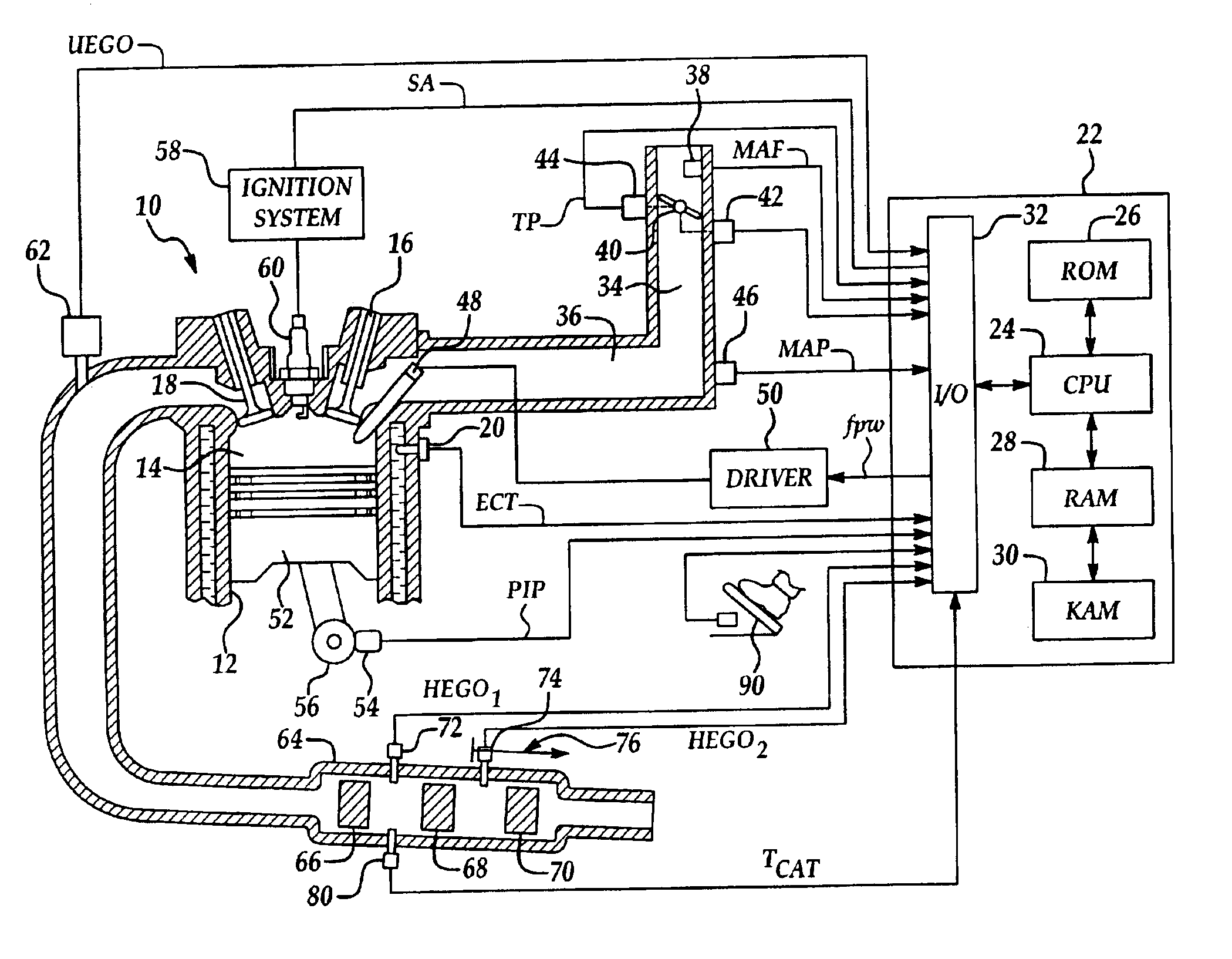
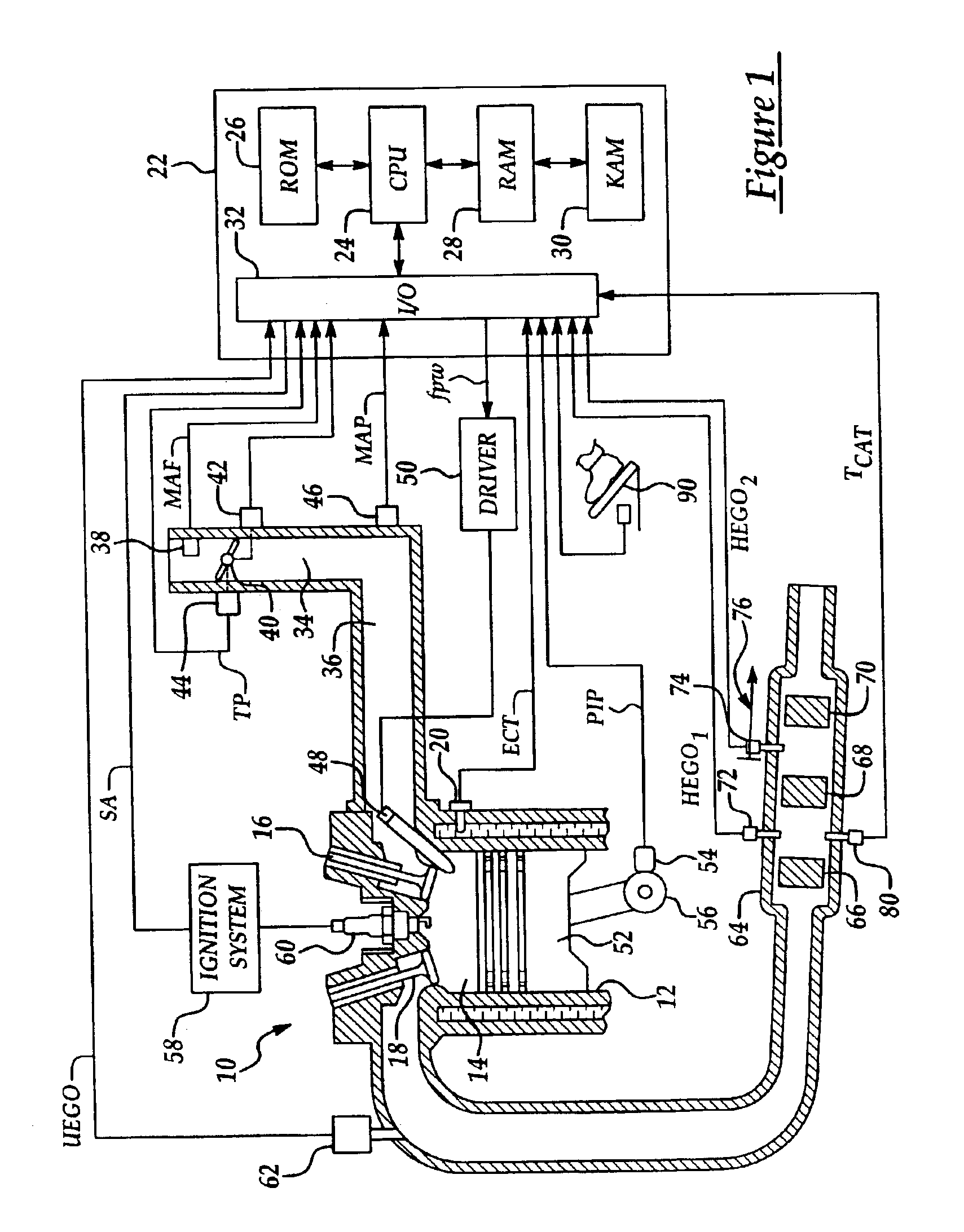
[0023]The present invention relates to a control strategy for controlling and monitoring operation of an internal combustion engine to effectively manage catalyst conversion efficiency under various engine, vehicle, and catalyst operating conditions. As will be appreciated by those of ordinary skill in the art, the various controllers referred to in describing the present invention are preferably implemented by software, code, or instructions executed by a microprocessor based engine, vehicle, or powertrain controller.

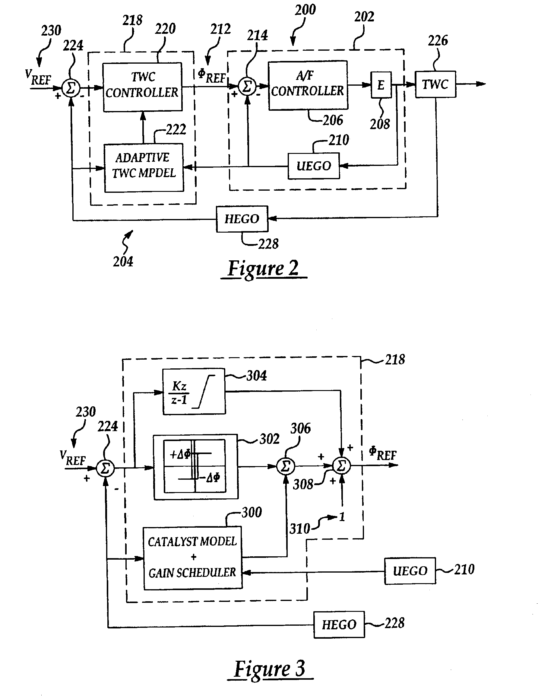
[0024]Embodiments of the invention use an inner feedback control loop for fuel / air ratio control and an outer feedback control loop that provides a fuel / air ratio reference value to the inner feedback control loop. The outer loop includes an adaptive controller that adapts to the estimated oxygen storage capacity of the catalyst, exerting more control effort while the catalyst exhibits a large degree of oxygen storage, while reducing control effort under higher engine...


PUM


Abstract

A system and method for controlling an internal combustion engine for low emissions include an inner feedback control loop to control the engine fuel / air ratio with feedback provided by a first exhaust gas sensor and an outer feedback control loop that modifies a reference fuel / air ratio provided to the inner feedback control loop based on feedback signals provided by a second exhaust gas sensor positioned downstream relative to a portion of the catalyst and a third exhaust gas sensor positioned downstream relative to the second exhaust gas sensor. Catalyst gains are determined by modeling the catalyst as an integrator with an unknown gain and estimating the catalyst gain based on the exhaust gas sensors with the gain used to monitor catalyst performance and / or modify the engine fuel / air ratio.

Description

CROSS-REFERENCE TO RELATED APPLICATIONS[0001]This application is related to commonly owned, concurrently filed, and copending U.S. patent application Ser. No. 10 / 454,059 titled Fuel / Air Ratio Peedback Control With Catalyst Gain Estimation for an Internal Combustion Engine and Ser. No. 10 / 454,121 titled Engine Control and Catalyst Monitoring Based on Estimated Catalyst Gain, the disclosures of which are hereby incorporated by reference in their entirety.BACKGROUND OF THE INVENTION[0002]1. Field of the Invention[0003]The present invention relates to a system and method for controlling an internal combustion engine.[0004]2. Background Art[0005]Internal combustion engines often employ advanced control strategies and after-treatment systems to reduce tailpipe emissions. Conventional closed-loop feedback control strategies have been used to control the fuel / air ratio of the engine to balance engine performance, fuel economy, and emissions. When using an after treatment system that include...

Claims


Application Information

Patent Timeline
Patent Type & Authority Patents(United States)
IPC IPC(8): F01N11/00F01N7/00F01N7/02F01N13/02F02D41/02F02D41/14
CPCF01N11/002F01N11/007F02D41/0295F01N13/0097F02D41/1477F01N2550/02F02D2200/0816Y02T10/47F02D41/1456Y02T10/40
Inventor MAKKI, IMAD HASSANSURNILLA, GOPICHANDRAKERNS, JAMES MICHAELSMITH, STEPHEN B.
Owner FORD GLOBAL TECH LLC
Why Eureka
Try Eureka