
Configurable multi-point sampling method and system for representative gas composition measurements in a stratified gas flow stream

a multi-point sampling and stratified gas flow stream technology, applied in the field of spatially representative fluid sampling methods and systems, can solve the problems of inconvenient continuous monitoring system manual process, laborious and time-consuming sampling process, and non-representative gas sampling in exhaust streams

Inactive Publication Date: 2005-06-14
GENERAL ELECTRIC CO
View PDF10 Cites 89 Cited by
  • Summary
  • Abstract
  • Description
  • Claims
  • Application Information

AI Technical Summary

Benefits of technology

"The patent describes a method and system for obtaining a representative sample of fluid flowing through a duct. The method involves positioning two sample probes in the duct and controlling the flow of fluid through each probe based on the concentration of a component species during a test. The two samples of fluid collected by the probes are then combined to create a spatially representative sample. The technical effect of this invention is to provide a reliable and accurate way to sample fluid in ducts, which can be useful in various applications such as industrial process monitoring and environmental monitoring."

Problems solved by technology

Non-representative gas sampling in exhaust streams is a significant contributor to inaccurate low level gas species (emissions) measurements.
This current process is generally a manual process that is not suitable for continuous monitoring systems.
This sampling process is thus laborious and time consuming as it requires multiple measurements to determine the gas velocity and then full-time attendance of a sample metering pump to draw flow through a port of known area at specific flow rates.
However, because it involves a common sample line, this approach does not allow easy and on-line adjustment of the flow rate sampled at each point.
However, it does not provide an isokinetic flow.
In these cases, sampling further into a flow stream would have higher line pressure losses and lower sampling rates.

Method used


Image

  • Configurable multi-point sampling method and system for representative gas composition measurements in a stratified gas flow stream
  • Configurable multi-point sampling method and system for representative gas composition measurements in a stratified gas flow stream
  • Configurable multi-point sampling method and system for representative gas composition measurements in a stratified gas flow stream

Examples


Embodiment Construction

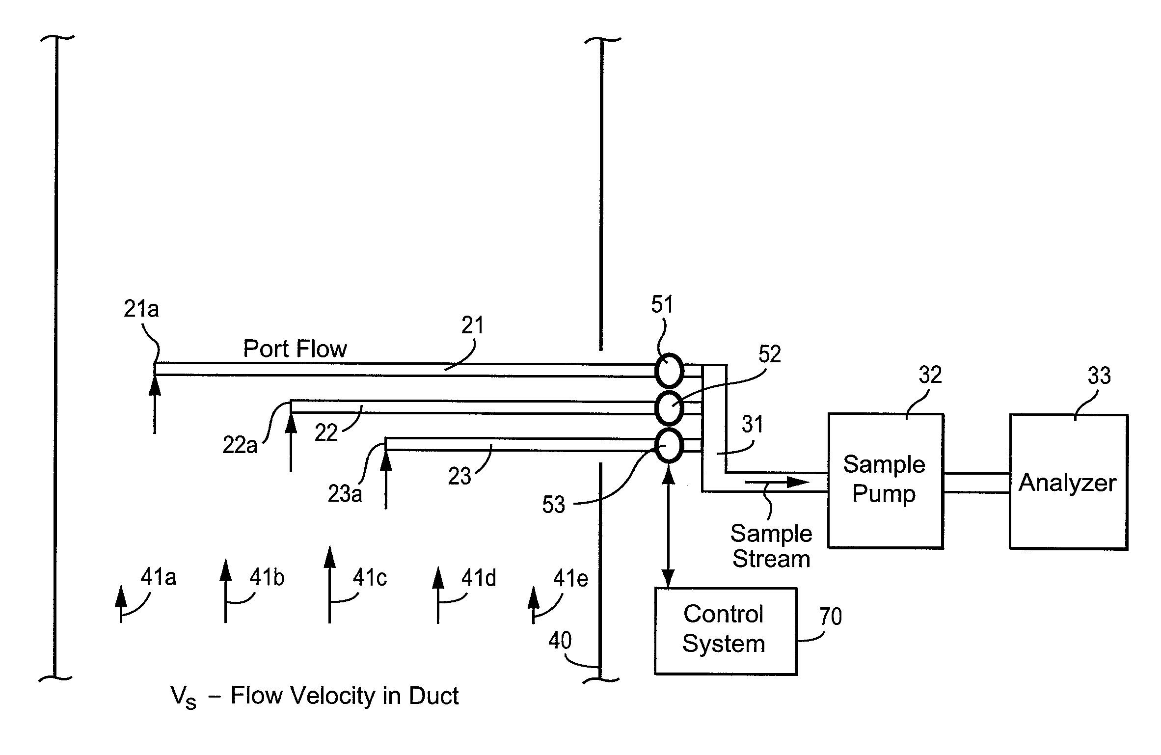
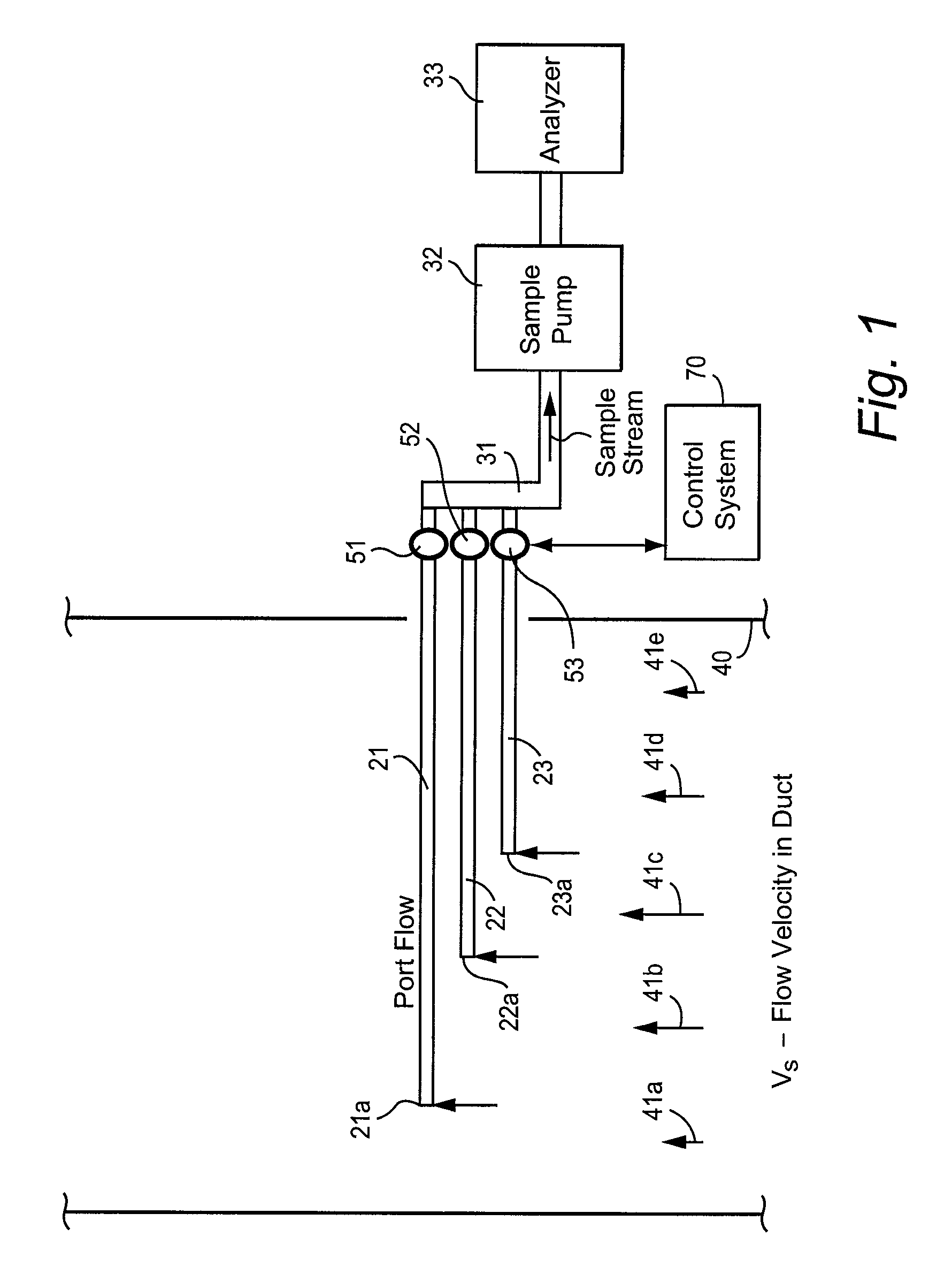
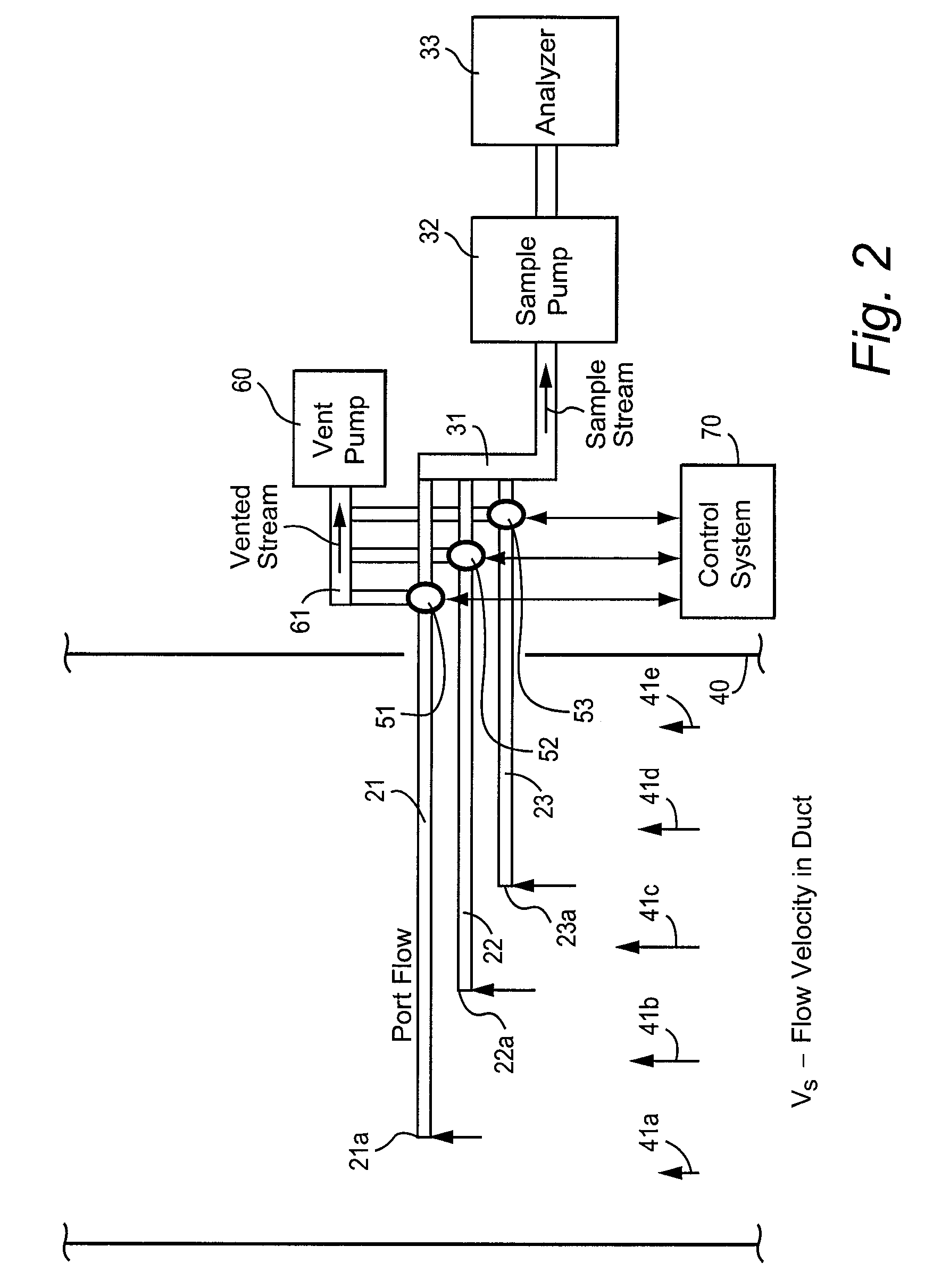
[0017]FIG. 1 illustrates an exemplary embodiment of a fluid sampling and monitoring system for obtaining a continuous and spatially representative sample of fluid flowing through duct 40. The fluid flowing through duct 40 may be, for example, exhaust gas containing pollutants from a gas turbine. Duct 40 may be, for example, an outlet exhaust stack of the gas turbine.

[0018]The sampling and monitoring system includes a plurality of sample probes 21–23, a plurality of flow controllers 51–53, sample pump 32 and sample analyzer 33. Sample probes 21–23 are spatially distributed within duct 40 and include inlet ports 21a–23a for receiving a sample of the fluid flowing through duct 40 at respective local positions. Sample passageway 31 fluidly connects flow controllers 51–53 and sample pump 32. Sample analyzer 33 is fluidly connected to sample pump 32.

[0019]A fluid flows through duct 40 at flow velocity Vs. However, the flow velocity of the fluid within different areas of duct 40 is often s...


PUM

PropertyMeasurementUnit
concentrationaaaaaaaaaa
concentrationsaaaaaaaaaa
flow rateaaaaaaaaaa

Abstract

A method and system of obtaining a sample of fluid flowing through a duct comprises determining an average concentration of a component species of the fluid during a test including determining first and second concentrations of the component species at first and second respective duct locations, positioning first and second sample probes in the duct so that they receive the fluid at the first and second locations, respectively, and controlling respective flow rates of fluid received by the first and second sample probes, or alternatively first and second time amounts that the flow of fluid is received by the first and second sample probes, respectively, based on the determined first, second and average concentrations. The respective flow rates or time amounts may be controlled so that component species concentration collectively received by the first and second sample probes equals the average concentration of the component species determined during the test.

Description

CROSS REFERENCE TO RELATED APPLICATIONS[0001]This application is related to commonly assigned U.S. application Ser. No. 10 / 605,795 entitled “A Multi-point Sampling Method for Obtaining Isokinetic Fluid Composition Flows in a Non-Uniform Velocity Flow Field”, filed concurrently herewith and naming Neil C. Widmer as inventor, the contents of which are incorporated herein by reference.BACKGROUND OF INVENTION[0002]The present invention relates to a method and system of obtaining a spatially representative sample of fluid flowing in a duct, and particularly relates to a method and system of obtaining a spatially representative sample of fluid utilizing multiple sampling probes.[0003]Emissions flowing in an exhaust stack of a gas turbine have been routinely sampled for many years. This sampling may indicate when emissions contain certain concentrations of pollutants. It is thus necessary to ensure that the emissions are sampled accurately.[0004]Non-representative gas sampling in exhaust s...

Claims


Application Information

Patent Timeline
Patent Type & Authority Patents(United States)
IPC IPC(8): G01N1/22G01N1/26
CPCG01N1/2258G01N2001/2285G01N2001/225G01N1/26
Inventor WIDMER, NEIL COLIN
Owner GENERAL ELECTRIC CO
Learn More