Low-contact area cutting element

a cutting element and low contact area technology, applied in drill bits, earthwork drilling and mining, construction, etc., can solve the problem of more diamond surface at the cutting tip, and achieve the effect of reducing residual stress, good cutting structure, and increasing the penetration rate of the drill bi

Inactive Publication Date: 2005-06-14
VAREL INT IND
View PDF25 Cites 43 Cited by
  • Summary
  • Abstract
  • Description
  • Claims
  • Application Information

AI Technical Summary

Benefits of technology

[0014]It has long been a goal in the drilling of bore hole formations to increase the penetration rate of the drill bit by faster drilling for the same amount of weight placed on the drill bit. A further technical advantage of the present invention is that a cutting element in accordance with the present invention has a smaller area in contact with the rock formation, thereby resulting in a deeper penetration for the same amount of weight applied. Further, the shape of the diamond layer of the cutting element results in more diamond surface at the cutting tip than exists in conventional cutter elements. This results in a sharper pointed cutter element (with more diamond at the edge) that maintains good cutting structure at least as long as a less sharp rounded cutting element.
[0015]Another technical advantage of the present invention is achieved by placing more diamond material at the cutting edges which has an effect on the residual stress in the PDC layer. By use of a non-planar interface between the diamond layer and the carbide substrate, there is achieved a reduction in damaging residual stress. This enables a sharp, high concentration of diamond with a stronger supporting structure.

Problems solved by technology

Further, the shape of the diamond layer of the cutting element results in more diamond surface at the cutting tip than exists in conventional cutter elements.

Method used


Image

  • Low-contact area cutting element
  • Low-contact area cutting element
  • Low-contact area cutting element

Examples


Embodiment Construction

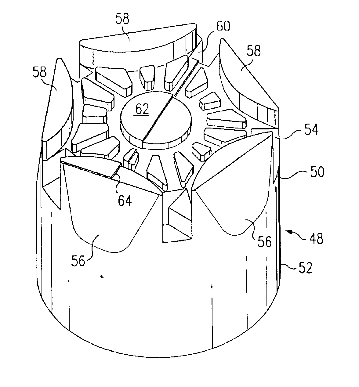
[0025]The present invention comprises an improved low contact area cutting element providing a cutter combining both shearing and tensile action while drilling bore holes in earth formations.

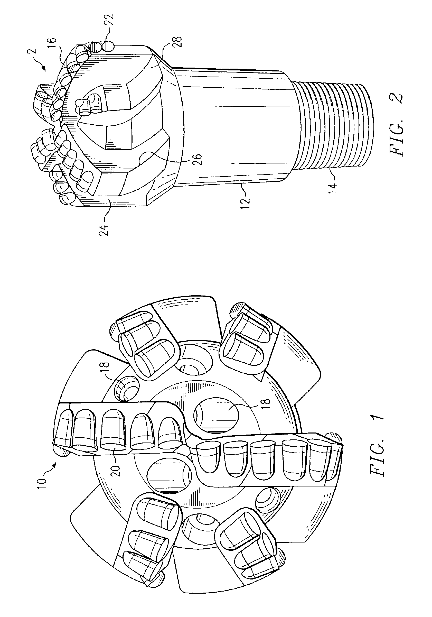
[0026]Referring to FIGS. 1 and 2, there is illustrated a drill bit 10 comprising at one end a shank 12 and a pin end 14 for connection to a drill string (not shown). Integral with the shank 12 at the end thereof opposite from the pin end 14, the drill bit defines a bit body 16. In the illustrated embodiment, bit body 16 has a substantially spherical segmented configuration although it is contemplated that the bit body 16 may have either a convex or concave bit face, or may alternately define a radial or conical surface. Opening through the bit face of the bit body 16 are a plurality of nozzles 18 extending through the bit body to a drilling mud passage within the shank 12. These nozzles enable drilling mud pumped through the drill string to be supplied to cutting elements 20 in accordance with c...


PUM


Abstract

A cutting element for a drag-type drill bit comprises a cutter body having a generally cylindrical base section adapted for snug-fitting engagement in a socket of a drill bit body. The cutter body is secured to the bit body by brazing or other conventional attachment techniques. The cutter body further has a generally cylindrical cutting section integral with the base section. The cutting section has at least one inclined surface extending from a top surface of the cutting section partially along the length of the generally cylindrical cutting section. The cutter body may comprise a sintered tungsten carbide and the top surface may comprise a layer of super hard material.

Description

TECHNICAL FIELD OF THE INVENTION[0001]The present invention relates to cutting elements for drag-type drill bits for drilling bore holes into subterranean formations. More particularly, the invention relates to drill bits and cutting elements therefor producing improved cutting forces for removal of cuttings from the front of a cutting element.BACKGROUND OF THE INVENTION[0002]Cutting elements having a polycrystalline diamond top surface are being utilized as the cutting or work portions of drilling or boring tools. Such cutting elements have been used in applications for drilling bore holes in subterranean formations in the mining, construction, oil and gas exploration, and the oil and gas production industries. There are many and varied forms and shapes of cutting elements currently being utilized with drill bits. One of the common insert shapes utilizes a cylindrical base section for insertion into the drill opening or socket of a drill bit body, with the upper or protruding porti...

Claims


Application Information

Patent Timeline
Patent Type & Authority Patents(United States)
IPC IPC(8): E21B10/46E21B10/56E21B10/567
CPCE21B10/5673
Inventor THIGPEN, GARY M.KEITH, CARL W.CUILLIER, BRUNO
Owner VAREL INT IND
Why Eureka
Try Eureka