Impeller for centrifugal compressors

a centrifugal compressor and compressor technology, which is applied in the direction of liquid fuel engines, marine propulsion, vessel construction, etc., can solve the problems of reducing the durability and reliability of the compressor, reducing the efficiency of the compressor, and increasing the mechanical load of the blade, so as to reduce the generation of separation flow from the splitter blade, preventing secondary flows, and reducing the effect of mechanical load

Inactive Publication Date: 2005-06-14
HONDA MOTOR CO LTD
View PDF5 Cites 36 Cited by
  • Summary
  • Abstract
  • Description
  • Claims
  • Application Information

AI Technical Summary

Benefits of technology

[0013]According to a preferred embodiment of the present invention, the blades include full blades and at least one splitter blade between each pair of adjacent full blades, a leading edge of each of the splitter blades being tilted toward the opposing suction surface of the adjacent full blade. This conforms the leading edge of the splitter blade to the oncoming flow which may contain a certain amount of separation flow created by the suction surface of the adjacent full blade so that the interference of the leading edge of the splitter blade with such a separation flow can be minimized.
[0014]In such a case, the splitter blade is preferably provided with a blade thickness which rapidly increases from a leading edge thereof as compared with a leading edge of the full blades. This prevents a creation of a sudden local increase in the inter-blade channel area or width, and generation of separation flow from the splitter blade can be minimized. According to a preferred embodiment of the present invention, the blade thickness of each splitter blade is asymmetric with respect to a neutral plane of the splitter blade. For instance, the splitter blade may include a section having a relatively constant thickness or a locally reduced thickness in a part somewhat downstream of the leading edge, preferably on the suction surface side of the splitter blade so that the angular change rate of the suction surface side of the splitter blade and hence the generation of separation flow therefrom may be minimized.
[0015]To the end of preventing secondary flows from the leading edge of each splitter blade, the leading edge of each of the splitter blade adjacent to the hub surface may be provided with a scallop portion.

Problems solved by technology

In particular, when the aerodynamic loading of a blade becomes excessive, particularly in the hub end of the blade, surging may occur owing to aerodynamic separation from the blade, and the efficiency of the compressor may be decreased owing to the generation of secondary flows.
Also, the mechanical loading of the blade tends to be increased, and the excessive mechanical stress in the hub end of each blade reduces the durability and reliability of the compressor.
However, increasing the tilt angle of the blade results in an increase in the mechanical stress of the hub end of the blade.
In other words, there is relatively little freedom in controlling the distribution of aerodynamic loading in the radial direction or from the tip end to the hub end of each blade, and this has prevented a further improvement in the performance of compressors for a given size thereof.
Because aerodynamic separation from the leading edges of the adjacent full blades tends occur more actively from the suction surface than the pressure surface, the leading edge of the splitter blade tends to interfere with the separation flow from the suction surface of the adjacent full blade, and this has a damaging effect to the efficiency of the compressor.

Method used


Image

  • Impeller for centrifugal compressors
  • Impeller for centrifugal compressors
  • Impeller for centrifugal compressors

Examples


Embodiment Construction

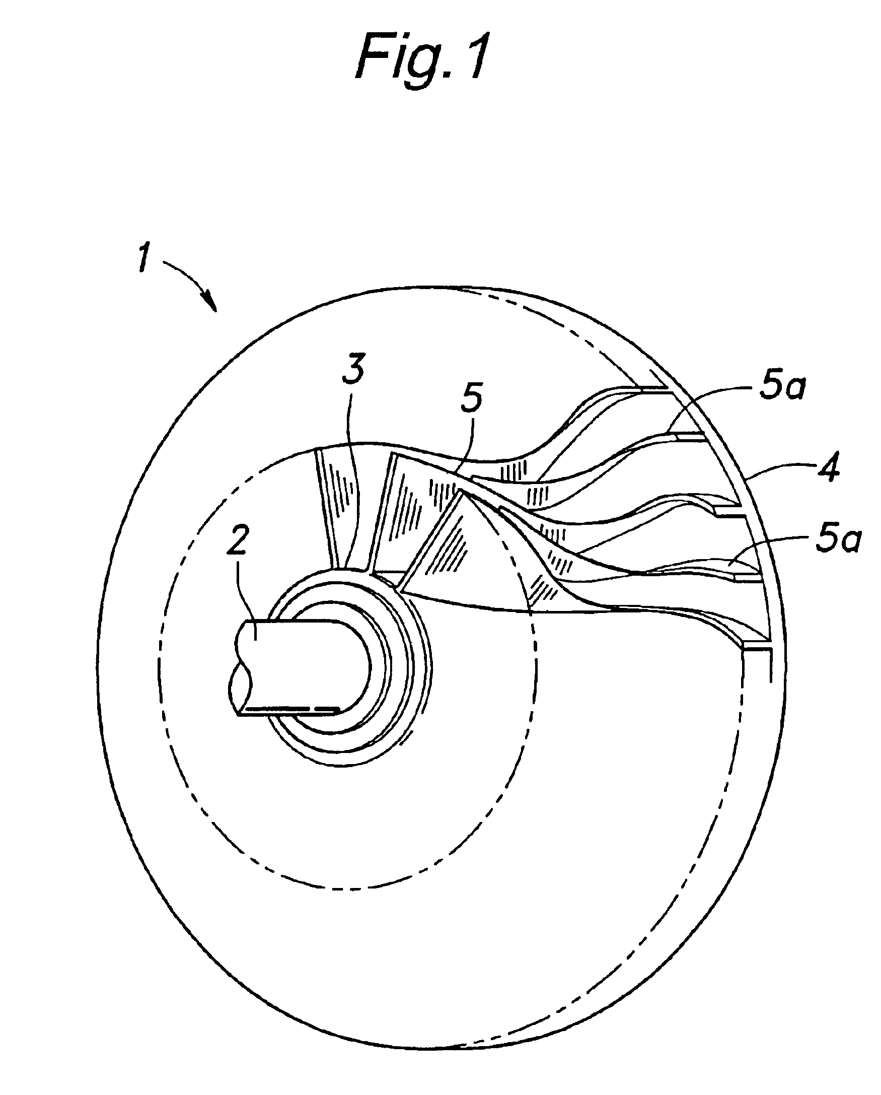
[0034]FIG. 1 is a fragmentary perspective view of an impeller of a centrifugal compressor embodying the present invention. The impeller 1 comprises a substantially frusto-conical hub 3 fixedly fitted on a rotor shaft 2, a disk 4 integrally and coaxially formed at the broader axial end of the hub 3 and a plurality of blades 5 and 5a projecting from a surface defined by the hub 3 and disk 4. The blades include full blades 5 and splitter blades Sa that are arranged in an alternating fashion along the circumference of the hub 3. Preferably, the hub 3, disk 4 and blades 5 and 5a are formed by machining a one-piece blank member made of titanium alloy or stainless steel. FIG. 1 shows only a part of the blades that are arranged over the entire circumference of the hub 3 at an equal interval.

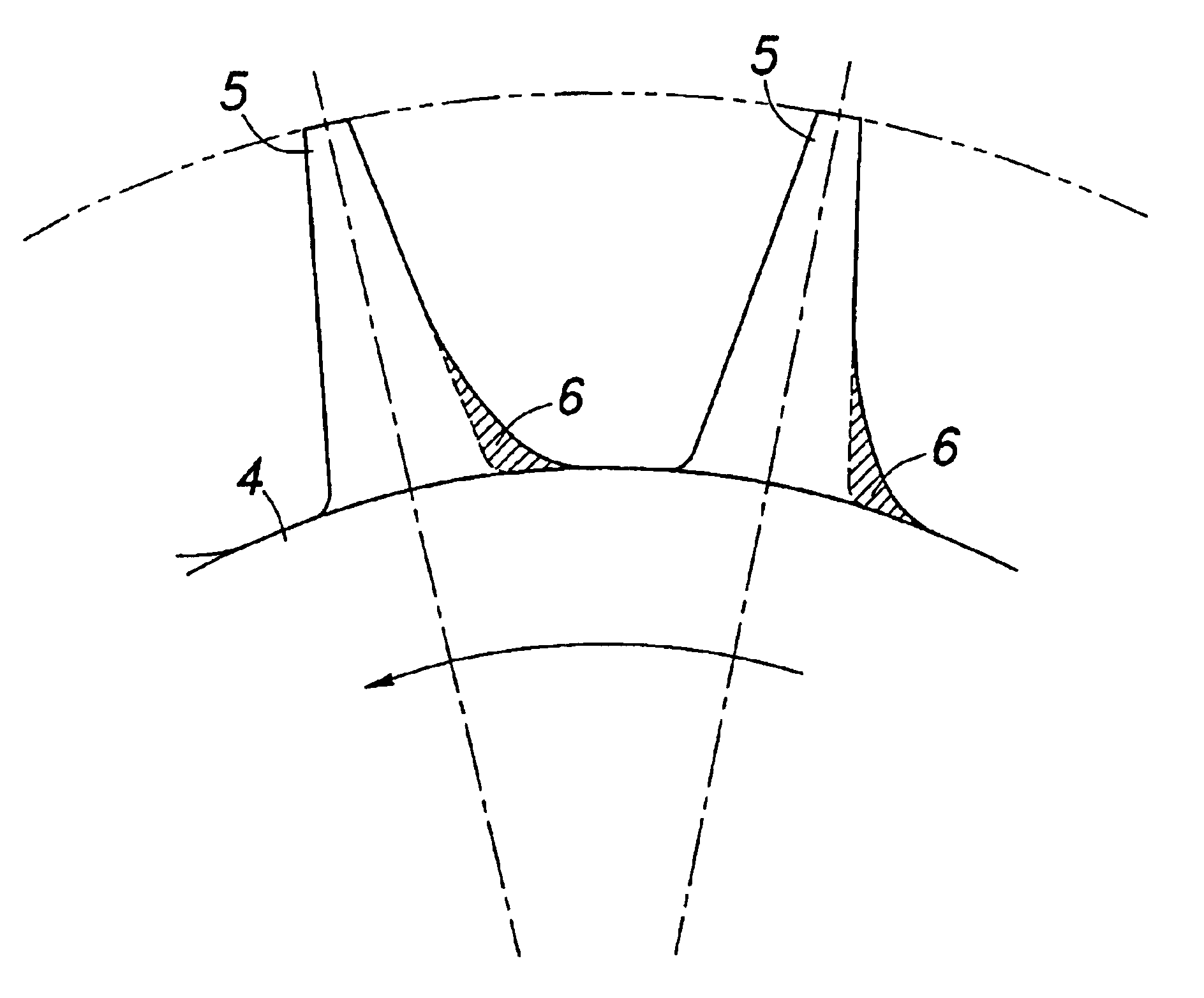
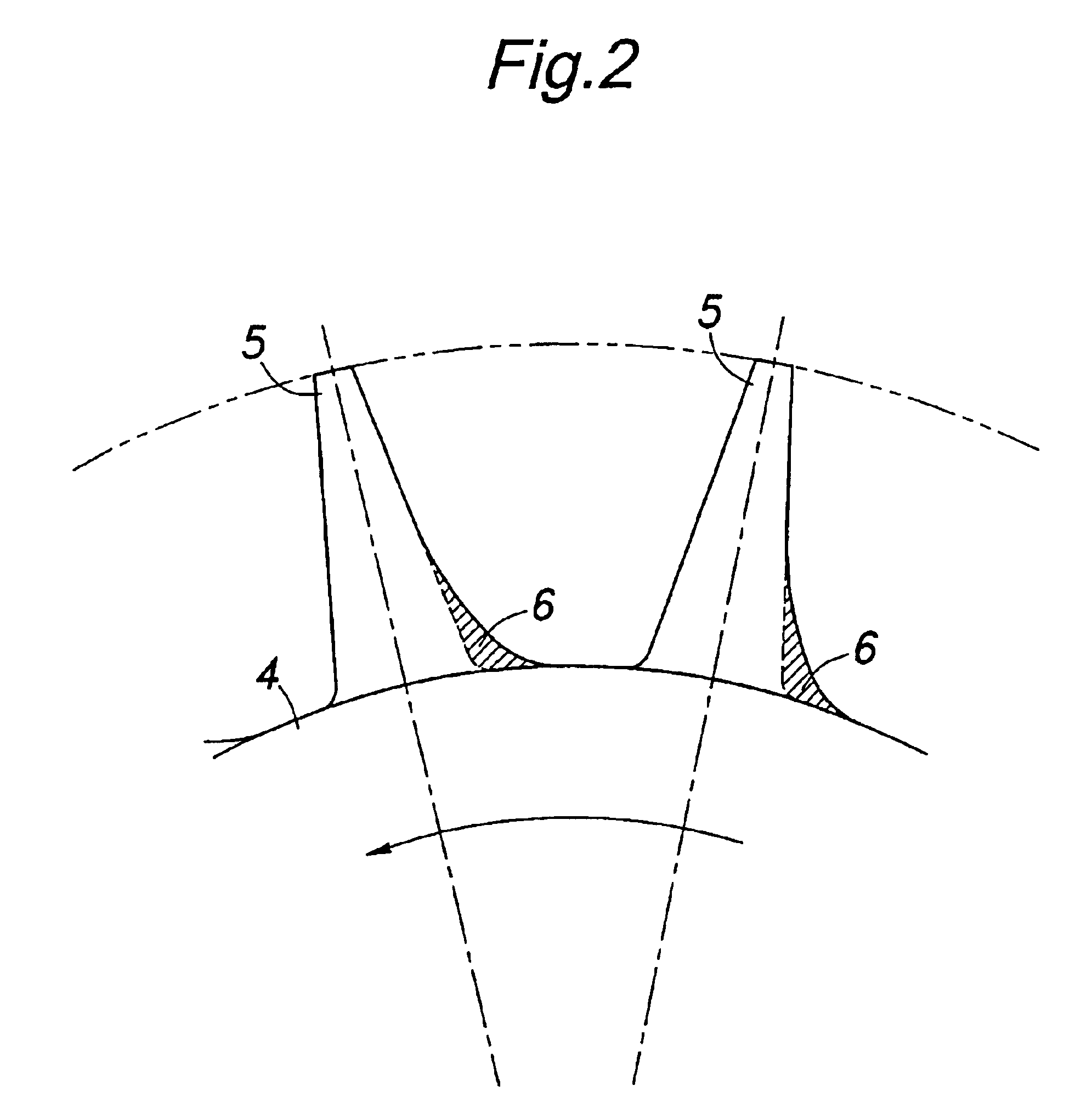
[0035]As shown in a somewhat exaggerated manner in FIG. 2, each blade has a substantially linearly increasing thickness from the tip end to the hub end, and is provided with a greater thickness on the si...


PUM


Abstract

In an impeller for centrifugal compressors comprising a plurality of blades each having a base end attached to a central hub, each of the blades is given with a thickness which increases progressively toward a hub end thereof, and a suction surface side of the blade is given with a greater thickness increase rate with respect to a neutral plane than a pressure surface side of the blade. Thereby, the inter-blade channel is narrowed locally in the region near the hub end of the suction surface of each blade, and this locally reduces the aerodynamic loading on the blade. In particular, the surge property is improved, and the generation of radially outwardly directed secondary flows can be minimized. This allows the distribution of aerodynamic loading in the radial direction or from the tip end to the hub end of each blade to be controlled at will, and enables the optimum design of the impeller.

Description

TECHNICAL FIELD[0001]The present invention relates to an impeller for centrifugal compressors comprising a plurality of blades.BACKGROUND OF THE INVENTION[0002]Centrifugal compressors that are used in superchargers for reciprocating engines and gas turbine engines are typically provided with an impeller comprising a substantially frusto-conical hub and a plurality of blades having base ends fixedly attached to the hub and defining surfaces that are twisted relative to the central axial line. Impeller design has a strong bearing on the compression efficiency, and various proposals have been made in connection with impeller design. Such an example can be found in Japanese patent laid open publication No. 07-91205.[0003]Each blade defines a suction surface and a pressure surface as it rotates fast with the hub. As can be readily appreciated, the mechanical stress in the blade tends to be high at the base end or hub end thereof. In particular, if the blade surfaces are tilted or leaned ...

Claims


Application Information

Patent Timeline
Patent Type & Authority Patents(United States)
IPC IPC(8): F04D29/28F04D29/30F04D29/66
CPCF04D29/284
Inventor KAWAMOTO, OSAMUOANA, MINEYASU
Owner HONDA MOTOR CO LTD
Why Eureka
Try Eureka