

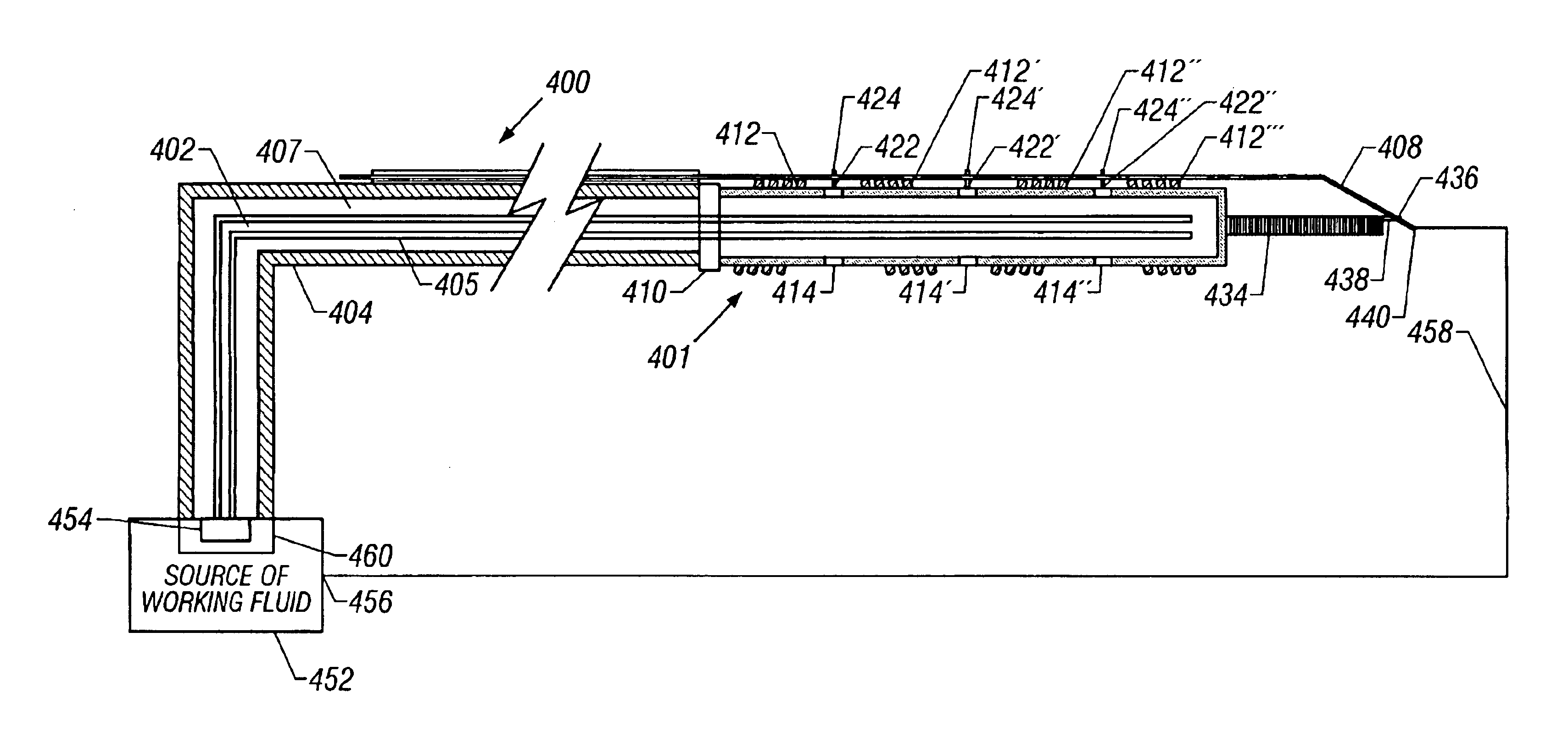
Selective organ cooling catheter with guidewire apparatus and temperature-monitoring device
- Summary
- Abstract
- Description
- Claims
- Application Information
AI Technical Summary
Benefits of technology
Problems solved by technology
Method used
Image

Examples
Embodiment Construction
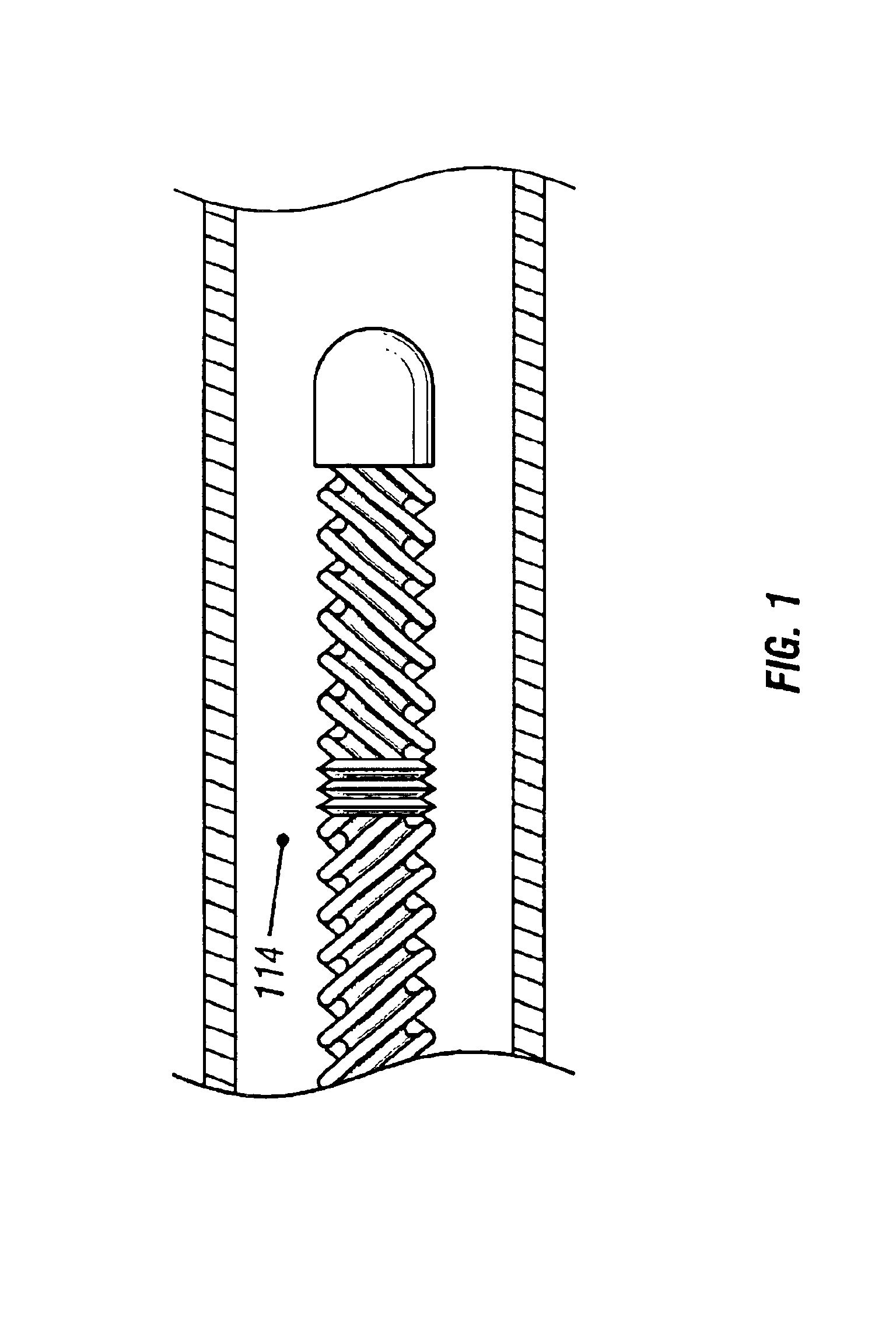
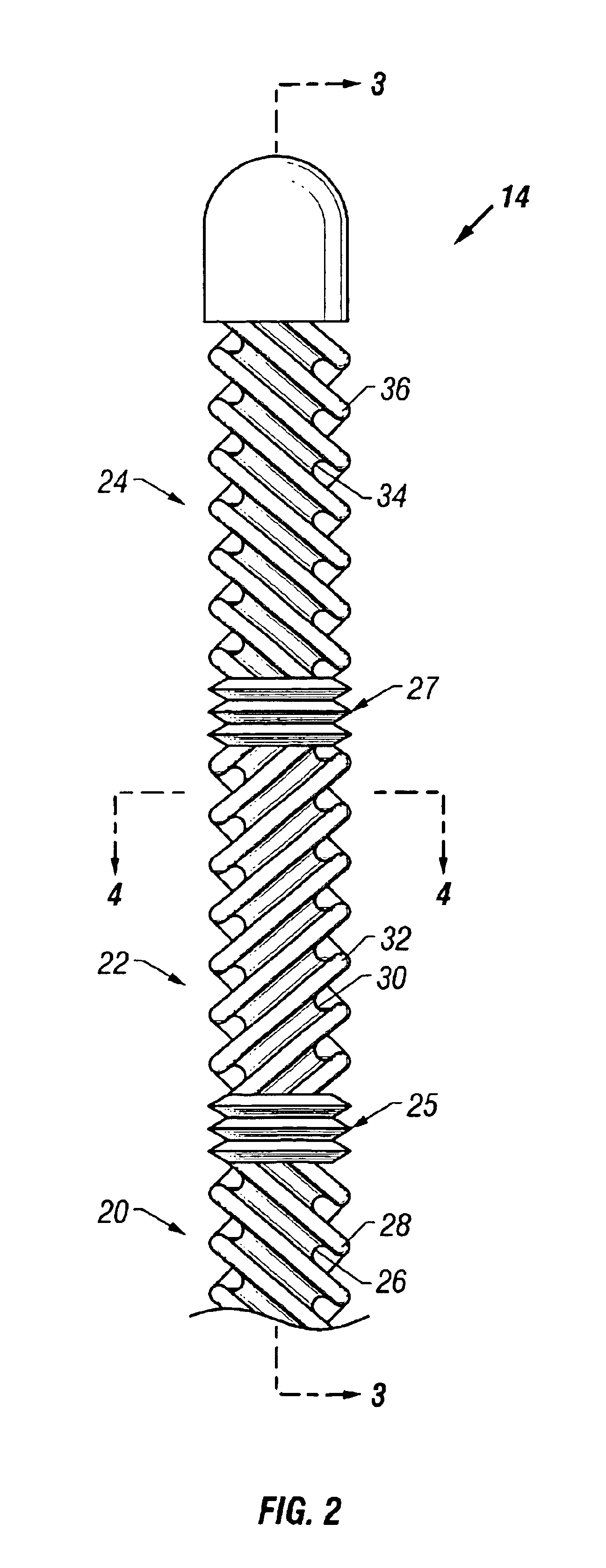
[0047]The temperature of a selected organ may be intravascularly regulated by a heat transfer element placed in the organ's feeding artery to absorb or deliver heat to or from the blood flowing into the organ. While the method is described with respect to blood flow into an organ, it is understood that heat transfer within a volume of tissue is analogous. In the latter case, heat transfer is predominantly by conduction.
[0048]The heat transfer may cause either a cooling or a heating of the selected organ. A heat transfer element that selectively alters the temperature of an organ should be capable of providing the necessary heat transfer rate to produce the desired cooling or heating effect within the organ to achieve a desired temperature.
[0049]The heat transfer element should be small and flexible enough to fit within the feeding artery while still allowing a sufficient blood flow to reach the organ in order to avoid ischemic organ damage. Feeding arteries, like the carotid artery,...
PUM
 Abstract
Description
Claims
Application Information