Feedback circuit and method of operating ballast resonant inverter

a ballast resonant inverter and feedback circuit technology, applied in the field of dc/ac inverters, can solve the problems of direct application of the above-mentioned controller, lamp power variation, and dead time variation

Inactive Publication Date: 2005-06-14
OSRAM SYLVANIA INC
View PDF9 Cites 31 Cited by
  • Summary
  • Abstract
  • Description
  • Claims
  • Application Information

AI Technical Summary

Benefits of technology

[0014]It is an object of the present invention to provide a novel method for optimized and stable operation of a ballast driven by a self-oscillating driver.
[0019]It is a still further object of the invention to provide reliable inverter operation in a periodical ON / OFF mode with pulse width modulation (PWM) dimming.

Problems solved by technology

However, driving MOSFET's with a sinusoidal voltage causes dead time variations followed by lamp power variations and other disadvantages.
However, with a preadjusted switching frequency that is not sensitive to transient variations and fluctuations of resonant frequency of the resonant load, direct application the above controllers has been troublesome.
Without correction of switching frequency, MOSFET's could have cross conduction and fail when operating below resonant frequency in some steady-state conditions, dimming mode or at lamp starting.
However, zero current sensing in any portion of the resonant load does not provide the necessary synchronization angle for optimized operation mode above the resonant frequency.
In addition, when used as a source of synchronization signals, the power diodes add significant power losses to the ballast.
It was found that the prior art inverter feedback circuit may cause excessive starting voltage and operation below the resonant frequency.
If it is used in a steady state mode, this positive feedback circuit creates instability.
In any obvious possible connection of current sensing diodes (in series with resonant capacitor, inductor, or lamp), it is difficult, or even impossible to achieve an optimum mode phase lock in a resonant inverter driven by self-oscillating AC.

Method used


Image

  • Feedback circuit and method of operating ballast resonant inverter
  • Feedback circuit and method of operating ballast resonant inverter
  • Feedback circuit and method of operating ballast resonant inverter

Examples


Embodiment Construction

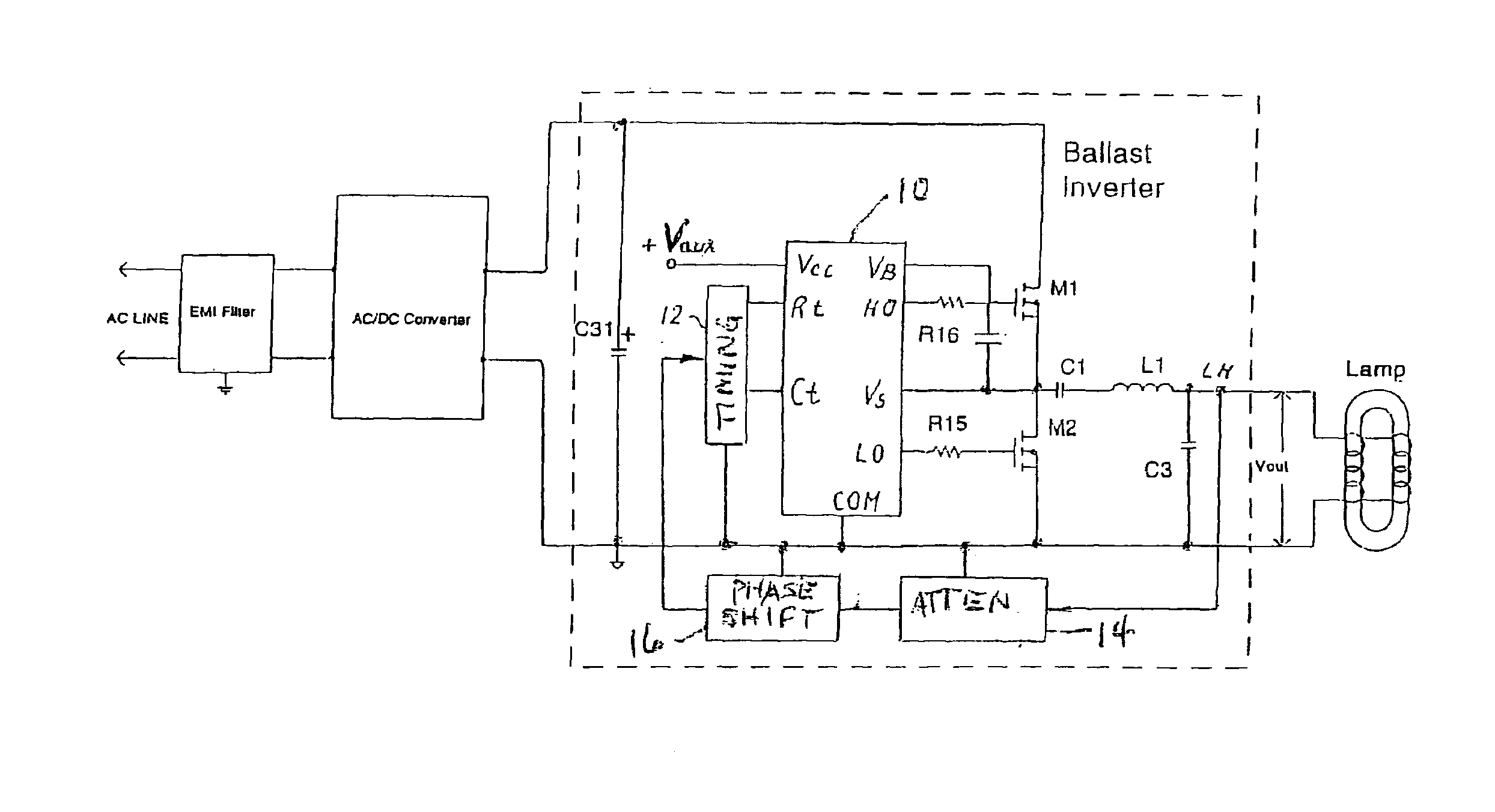
[0033]With reference now to FIG. 3, a self-oscillating driver IC 10 drives half bridge power stages with transistors M1 and M2 generating an AC voltage across the input of a resonant load. IC 10 has a built-in oscillator that is, or is similar to, the “555” timer of the prior art. Oscillator frequency can be programmed with a timing circuit 12 coupled to pins Rt, Ct and common “com”.

[0034]The feedback circuit includes blocks 14 and 16 that couple inverter high voltage output LH to timing circuit 12. Block 14 attenuates the output voltage signal and block 16 phase shifts the output voltage signal from 150° to 200° to compensate for the phase difference between the inverter output voltage and the external synchronization signal.

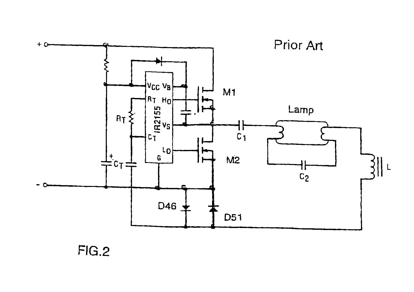
[0035]Timing circuit 12 may include a timing capacitor Ct and resistor Rt (see FIG. 2) and switches when the timing capacitor is charged to ⅔ Vcc and discharged to ⅓ Vcc. In a standard IC application, the timing capacitor voltage waveform is an exponential ramp...


PUM


Abstract

A ballast resonant inverter with a self-oscillating driver IC powers and dims a gas discharge lamp. A feedback circuit automatically adjusts IC oscillator frequency for safe and stable inverter operation above the resonant frequency following changes in the resonant load. The feedback signal is derived from resonant inverter output voltage, by attenuating, programmed phase shifting and injecting the resulting signal in a timing circuit of the IC. The feedback circuit includes an active inverter circuit or passive RC phase boosting networks coupled in series. Phase control of the feedback signal by variable RC networks is used in transient modes of ballast-lamp operations.

Description

BACKGROUND OF THE INVENTION[0001]The present invention relates to electronic ballasts for powering gas discharge lamps and particularly to DC / AC inverters for energizing and dimming gas discharge lamps, including inductively coupled gas discharge lamps.[0002]A gas discharge lamp typically utilizes an electronic ballast for converting AC line voltage to high frequency current for powering the lamp. Conventional electronic ballasts include an AC to DC converter and a resonant inverter converting DC voltage to lamp high frequency current. The resonant inverter includes switching transistors generating a high frequency rectangular AC voltage that is applied to a voltage resonant circuit having an inductor and a capacitor in series. The gas discharge lamp is coupled in parallel to the capacitor. For high frequency electronic ballasts, a self-oscillating resonant inverter is a common part that generates AC voltage for starting and AC current for powering the lamp. Self-oscillating resonan...

Claims


Application Information

Patent Timeline
Patent Type & Authority Patents(United States)
IPC IPC(8): H05B41/28H05B41/285
CPCH05B41/2813H05B41/2856Y10S315/07Y02B20/186Y02B20/22Y02B20/185Y02B20/00
Inventor ALEXANDROV, FELIX I.
Owner OSRAM SYLVANIA INC
Why Eureka
Try Eureka