

Gas turbine engine starter generator with multiple windings on each exciter stator pole
- Summary
- Abstract
- Description
- Claims
- Application Information
AI Technical Summary
Benefits of technology
Problems solved by technology
Method used
Image

Examples
Embodiment Construction
[0022]Before proceeding with the detailed description, it is to be appreciated that the present invention is not limited to use in conjunction with a specific type of electrical machine. Thus, although the present invention is, for convenience of explanation, depicted and described as being implemented in a brushless AC (alternating current) motor / generator, it will be appreciated that it can be implemented in other AC motor / generator designs needed in specific applications.
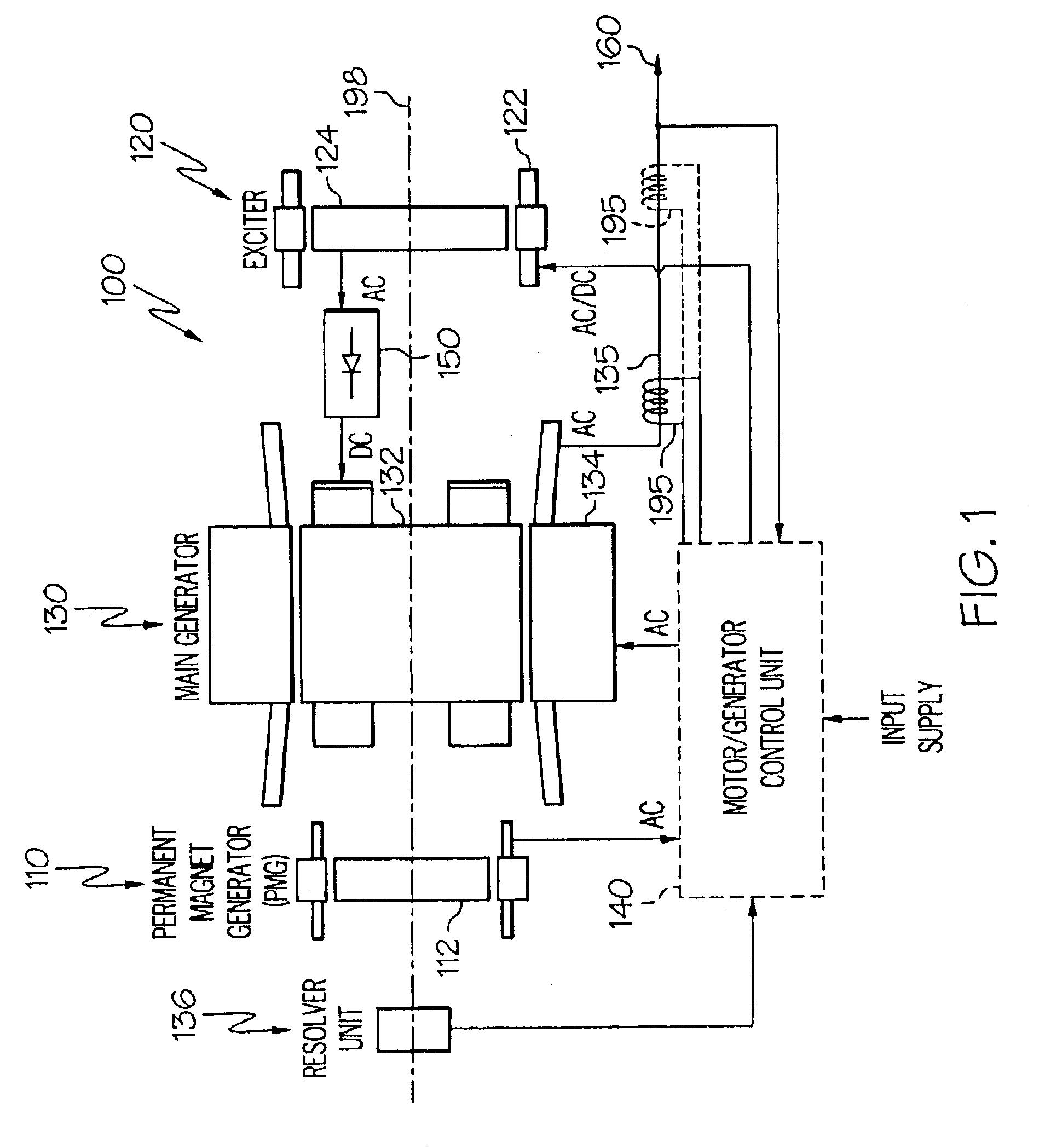
[0023]Turning now to the description, and with reference first to FIG. 1, a functional schematic block diagram of one embodiment of a high speed motor / generator system 100 is shown. This exemplary motor / generator system 100, which is commonly known as a brushless AC motor / generator, includes a permanent magnet generator (PMG) 110, an exciter 120, a main motor / generator 130, a motor / generator control unit 140, and one or more rectifier assemblies 150. It is noted that the motor / generator system 100 may be used as ...
PUM
 Abstract
Description
Claims
Application Information