
Device and method for the detection of a charging voltage

a charging voltage and device technology, applied in secondary cell servicing/maintenance, instruments, transportation and packaging, etc., can solve the problems of overcharged accumulation, damage, and, therefore, obvious more expensive in comparison with 8 bit a/d converters, and achieve correspondingly flexibly, compact and inexpensive effects

Active Publication Date: 2005-06-14
FRIWO GERAETEBAU GMBH
View PDF4 Cites 14 Cited by
  • Summary
  • Abstract
  • Description
  • Claims
  • Application Information

AI Technical Summary

Benefits of technology

[0014]It is an object of the present invention to provide a device for detecting the charging voltage of at least one rechargeable battery, which can be manufactured correspondingly flexibly, compact and inexpensively, as well as a corresponding method therefor.
[0016]The present invention is based on the knowledge that, on one hand, complex analog circuits can be simplified by the use of modern evaluation and control devices, e.g. microcontrollers, and that, on the other hand, complicated and, thus, expensive evaluation and control devices can be replaced by essentially more inexpensive ones by using efficient and compact analog circuits.
[0017]Therefore, extremely compact, inexpensive chargers can be realized on the basis of the solution according to the invention, which, on one hand, can be used for one or more rechargeable batteries. On the other hand, the accuracy in the detection of the cell voltage according to the inventive solution allows the control of the charging process of the accumulator cells with such an exactness that the overcharge of the accumulator cells is reduced to a minimum, so that the service life of the accumulator cells is increased.
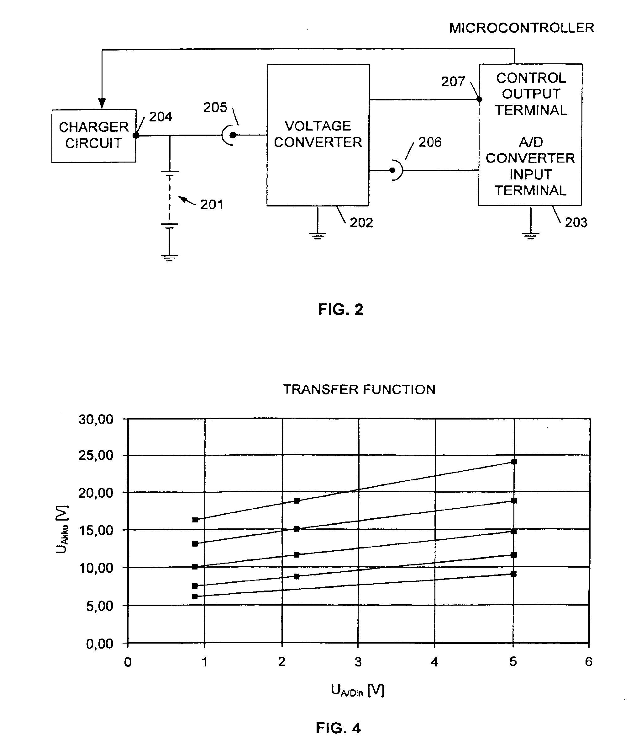
[0019]This compact circuit allows the flexible adjustment of the voltage signal of the accumulator cells to the input voltage range of the A / D converter during the charging process. This permits, on one hand, an exact detection of the accumulator cell voltage and, thus, a precise control of the charging process by means of an 8 bit microcontroller. On the other hand, this preferred embodiment permits, either with a minimum or a maximum number of accumulator cells to be charged, the detection of the maximum charging state of the batteries with an accuracy to such an extent that overcharging is avoided. The compact construction of the circuit allows space-saving and miniaturized embodiments of the present invention, which can moreover even be realized in an inexpensive manner due to the use of 8 bit microcontrollers.
[0020]If an overlapping of the gain ranges is provided in addition to the inventive solution, a continuous transition between the gain ranges is feasible without the occurrence of evaluation errors in the measurement of the accumulator cell voltage, which entails the faulty control of the charging process of the accumulator cells.
[0022]This particularly preferred embodiment once more reduces the size of the circuitry in comparison with the already mentioned one, as one control output terminal is enough to control the gain of the control output terminal, which is preferably integrated in the evaluation and control device. An adjustment of the duty cycle of the pulse width modulation circuit step by step therefore additionally allows a nearly continuous gain, by which the accuracy of the detection of the accumulator cell voltage is once more improved.

Problems solved by technology

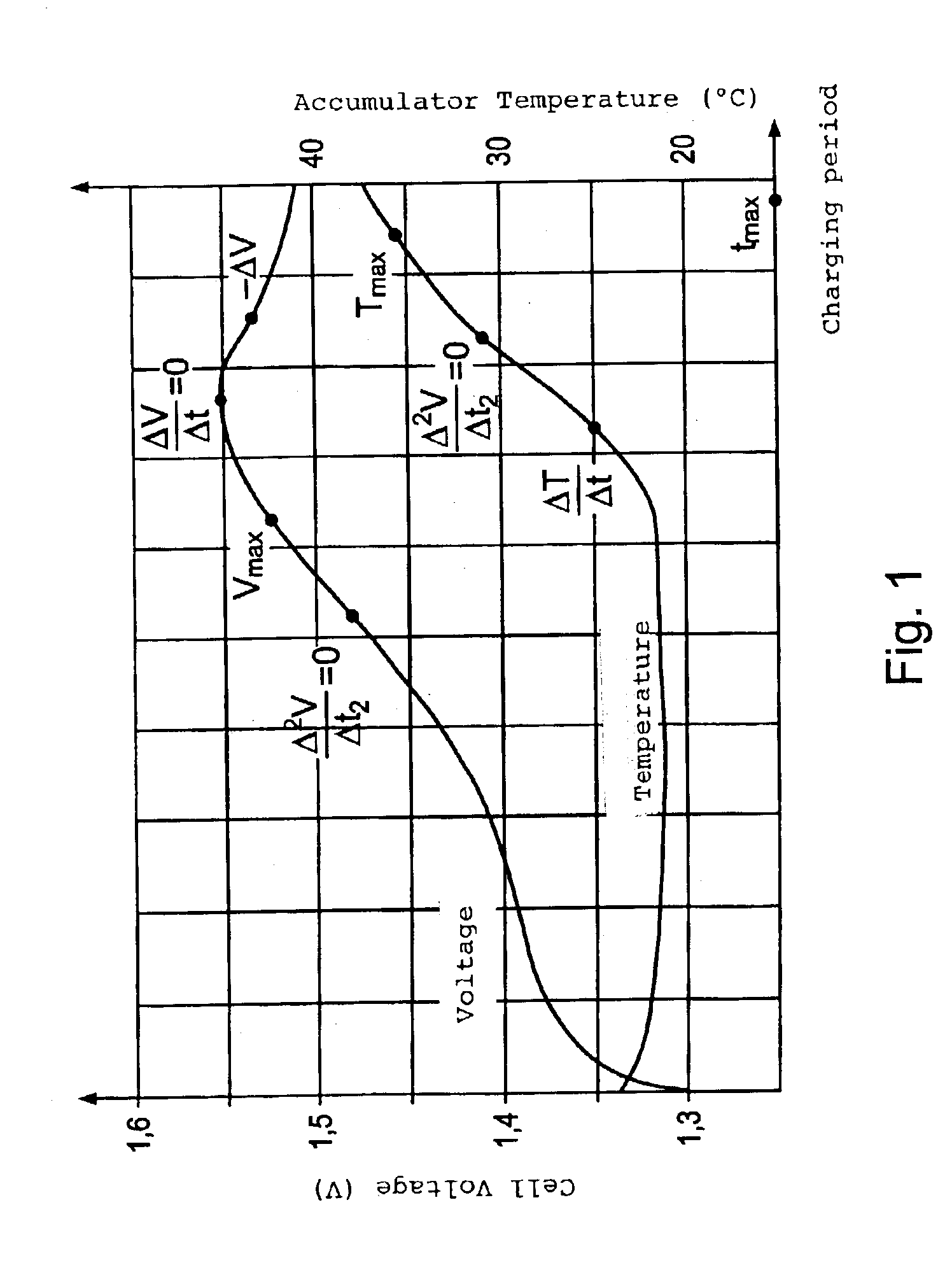
Any additional charging beyond this point signifies that the accumulator is overcharged and, thus, damaged.
Relative to a definite number of accumulator cells the demand for accuracy in the −ΔU detection of at least 0.33% can, therefore, only be maintained by a 10 bit A / D converter, which is, however, clearly more expensive in comparison with an 8 bit A / D converter.

Method used


Image

  • Device and method for the detection of a charging voltage
  • Device and method for the detection of a charging voltage
  • Device and method for the detection of a charging voltage

Examples


Embodiment Construction

[0035]The illustrative embodiments of the present invention will be described with reference to the figure drawings, wherein like elements and structures are indicated with like reference numbers.

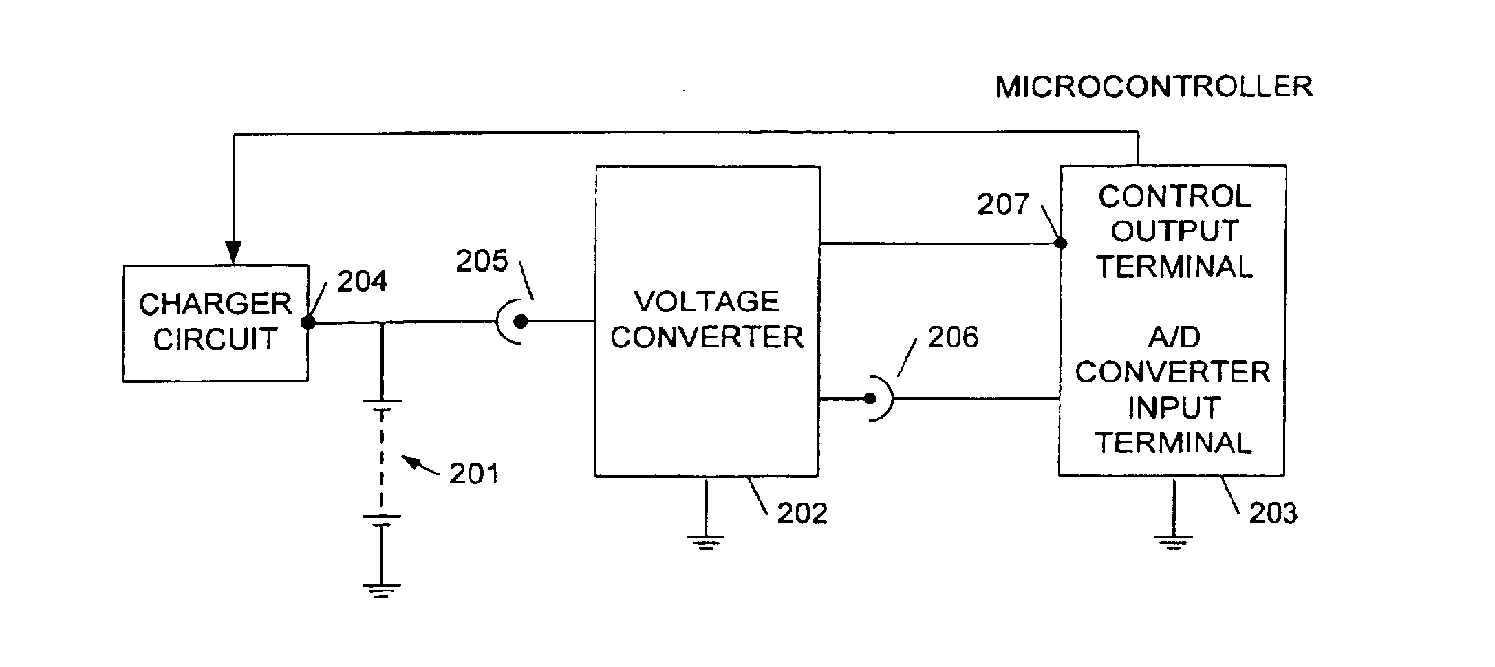
[0036]FIG. 2 shows, by means of a simple block diagram, a preferred embodiment of the present invention. The block diagram shows a block with accumulator cells 201, a voltage converter 202 and an evaluation and control device 203. In the present embodiment, an 8 bit microcontroller, in which the A / D converter is integrated, has been chosen as an inexpensive example for the evaluation and control device. Embodiments comprising the aforementioned features, in which a separate A / D converter or a different evaluation and control device are used, are also possible, however.

[0037]The accumulator cell block 201 comprises a terminal 204 for a charger for charging the accumulator cells and is connected to a voltage converter 202. Via an input terminal of the voltage converter the variable voltage 20...


PUM


Abstract

The present invention relates to a device and a method for the detection of a charging voltage of at least one rechargeable battery comprising a voltage converter for converting the charging voltage of the at least one rechargeable battery into a voltage signal, an analog / digital converter for converting the voltage signal of the voltage converter into a digital signal, and an evaluation and control device for evaluating the digital signal of the analog / digital converter as well as for controlling the charging process of the at least one rechargeable battery on the basis of the evaluation of the digital signal of the analog / digital converter. The voltage converter comprises an amplifier circuit with a variable gain controlled by at least one control output terminal of the evaluation and control device such that the gain applied for the generation of the voltage signal is adjusted to the input voltage range of the analog / digital converter according to a transfer function.

Description

BACKGROUND OF THE INVENTION[0001]1. Field of the Invention[0002]The present invention relates to a device and a method for the detection of a charging voltage of at least one rechargeable battery.[0003]2. Description of the Related Art[0004]Due to their manifold advantages mobile terminals in the electric and entertainment industries become increasingly important. These devices depend on a location-independent power supply and, for reasons relating to the expenses therefor and to the environment, it is recommendable to use rechargeable batteries (hereinafter called accumulator). At the same time, there is an increasing need for inexpensive and compact accumulator chargers, as the terminals, too, are constantly manufactured smaller in size and more inexpensively. On the other hand, the chargers have to be reliable and flexible enough to guarantee a long service life of the accumulators, and they have to be capable of charging a variable number of rechargeable batteries at the same ti...

Claims


Application Information

Patent Timeline
IPC IPC(8): G01R31/36H02J7/00G01R19/00H01M10/44H02J7/10
CPCG01R31/3648G01R31/362H02J7/0072H02J7/0052H02J7/0047G01R31/3835H02J7/007182H02J7/00
Inventor BREUCH, GEORGKUBACKI, ZBIGNIEW
Owner FRIWO GERAETEBAU GMBH
Learn More