Method and system for correcting non-linear response in amplifiers

a nonlinear response and amplifier technology, applied in the field of amplifiers, can solve problems such as decreasing the utility of compact electronic devices as part of compact devices, and achieve the effect of increasing the range of input voltages

Active Publication Date: 2005-06-14
CSR TECH INC
View PDF7 Cites 4 Cited by
  • Summary
  • Abstract
  • Description
  • Claims
  • Application Information

AI Technical Summary

Benefits of technology

[0003]In accordance with the present invention, an amplifier circuit maintains linearity using a correction circuit. This increases the range of input voltages under which the ampli

Problems solved by technology

In addition to increasing the noise of the amplifier, such components may also take up headroom

Method used


Image

  • Method and system for correcting non-linear response in amplifiers
  • Method and system for correcting non-linear response in amplifiers
  • Method and system for correcting non-linear response in amplifiers

Examples


Embodiment Construction

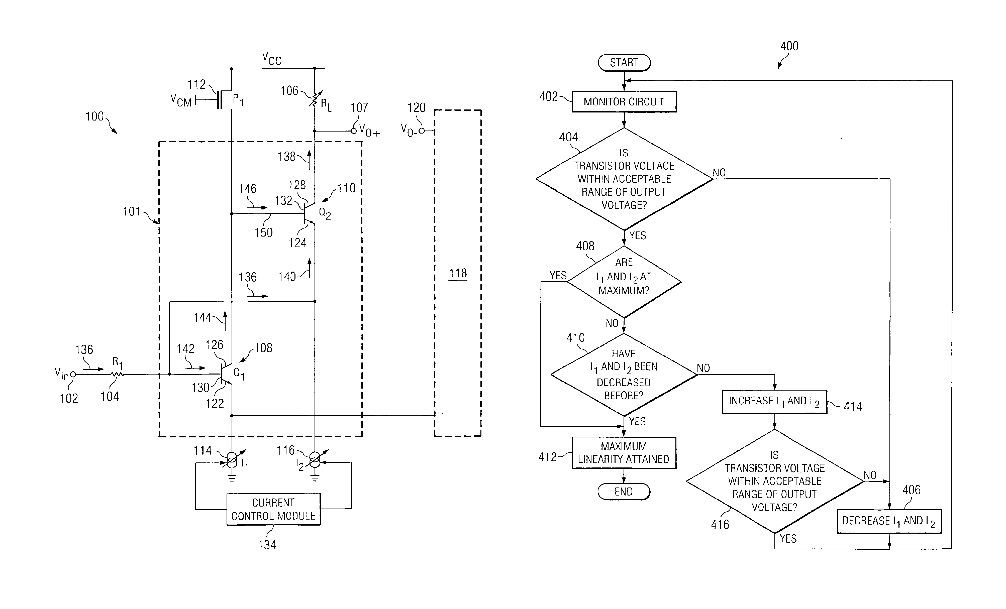
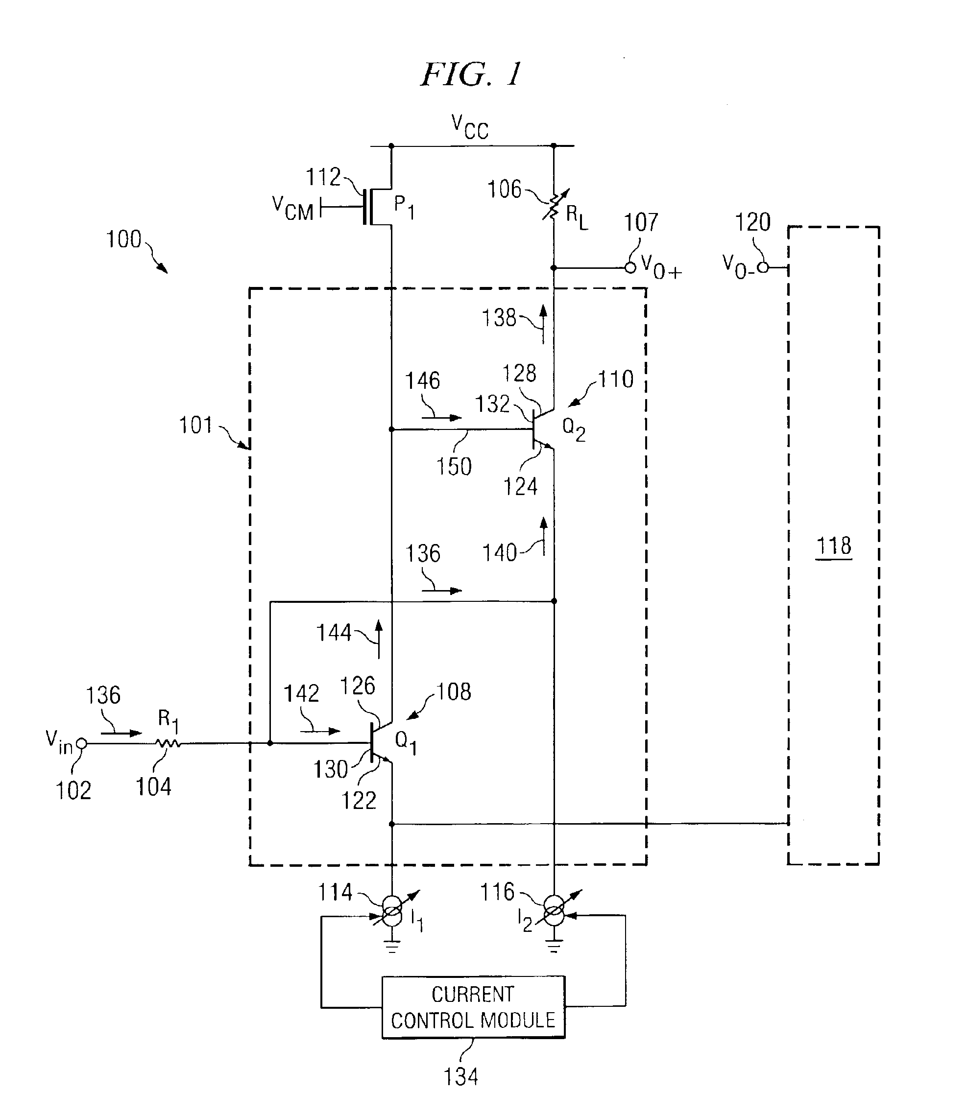
[0013]FIG. 1 illustrates an amplifier circuit 100 that includes a correction circuit 101, a resistor 104, a variable resistor 106, a constant current source 112, first variable bias current source 114, a second variable bias current source 116, and a current control module 134. Correction circuit 101 includes transistors 108 and 110 to provide corrections to non-linear fluctuations associated with amplifier circuit 100. Resistor 106, current sources 114 and 116, and current control module 134 operate to extend the linear range of operation of amplifier circuit 100. Circuit 100 also includes a mirror half circuit 118 that represents the mirror images of the components presented above.

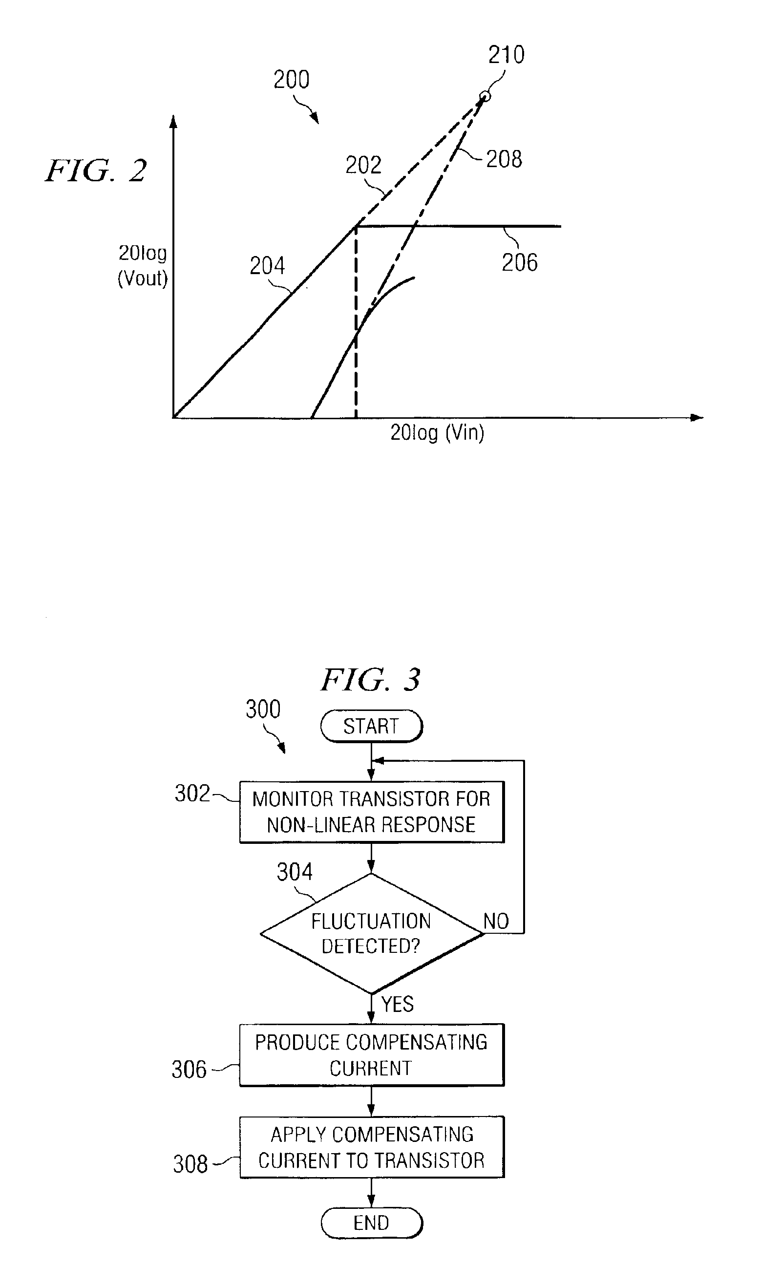
[0014]Before proceeding with the description of FIG. 1, it is useful to provide some description of the concept of linearity as applied to amplifiers. FIG. 2 is a graph 200 that illustrates the output third-order intercept (OIP3) 210 of an amplifier, a useful value for characterizing the linearity of the...


PUM


Abstract

A method for extending the linear range of operation of an amplifier includes monitoring a transistor voltage of a transistor of an amplifier. The transistor is coupled to a variable current source applying a bias current to the transistor. The method continues by monitoring an output voltage of the amplifier and by determining whether the transistor voltage is within a predetermined range of the output voltage. If the transistor voltage is not within a predetermined range of the output voltage, the method continues by decreasing the bias current applied to the transistor. If the transistor voltage is within a predetermined range of the output voltage and if the bias current has not previously been decreased, the method continues by increasing the bias current applied to the transistor.

Description

TECHNICAL FIELD OF THE INVENTION[0001]This invention relates in general to amplifiers, and more particularly to a method and system for correcting non-linear response in amplifiers.BACKGROUND OF THE INVENTION[0002]Amplifier design involves many diverse considerations. Such considerations include gain of the amplifier, noise figure, and linearity of amplifier response. Furthermore, in integrated circuit design, amplifiers may be limited in the amount of headroom available to components of the amplifier. It is desirable, therefore, to correct any non-linear responses in an amplifier without significantly increasing noise or requiring too much headroom.SUMMARY OF THE INVENTION[0003]In accordance with the present invention, an amplifier circuit maintains linearity using a correction circuit. This increases the range of input voltages under which the amplifier produces a linear output response. In particular, certain embodiments of the present invention use transistor feedback to correct...

Claims


Application Information

Patent Timeline
IPC IPC(8): H03F1/02H03F1/30H03F1/32
CPCH03F1/0272H03F1/302H03F1/32
Inventor WOMAC, MICHAEL D.
Owner CSR TECH INC
Why Eureka
Try Eureka