Method for polarization mode dispersion compensation

a technology of optical signals and dispersion compensation, applied in multiplex communication, instruments, optical elements, etc., can solve the problems of signal degradation, more complex optical signal effect, and pulse spreading

Inactive Publication Date: 2005-06-14
PROXIMON FIBER SYST
View PDF12 Cites 12 Cited by
  • Summary
  • Abstract
  • Description
  • Claims
  • Application Information

AI Technical Summary

Benefits of technology

[0024]The optical path length location of one or both of the reference reflection points is adjustably varied to compensate for polarization dispersion between the first and second orthogonal states of polarization. In an alternative embodiment, prior to the step of adjustably varying the optical path length from the second reflection point, the optical path length of at least one of the gratings may be pre-tuned such that one of the reflection points is either at substantially the same optical path length as the other reflection point or slightly ahead or behind (shorter or longer optical path length).

Problems solved by technology

This variation in velocity leads to pulse spreading and thus signal degradation.
This results in a more complex effect on the optical signal, which is characterized by the concept of “principal states of polarization” or PSPs.
Dispersion imposes serious limitations on transmission bandwidth, especially across long distances, such as in transoceanic routes.
PMD can become an inhibiting factor either limiting overall system length or increasing system costs due to the need for additional optical-to-electrical-to-optical signal conversion sites to permit electrical signal regeneration.
More importantly, the amount of PMD correction is fixed because of the fixed DGD of the PM fiber, limiting the adaptability and applicability of the system.
In addition, the overall speed of the variable delay element will be slow due to the mechanical movement of the optics.
Furthermore, since the variable delay is created outside of fiber there may be issues of cost and stability due to the complexity associated with the required active alignment of the optical beam.
In this case, the application of axial strain to the fiber changes the reflection location of each polarization at a different rate, thus changing the delay between them.
However, such a design can only achieve a limited range of delays because the differential delay is proportional to the small birefringence of the fiber, and is limited by the small range of strain that the fiber can withstand before breaking.
However, such a system does not account for polarization fading effects which will require dynamic polarization control in each of the SM fiber grating paths to assure that all light returns properly through the polarization splitter; this will substantially add to the complexity and cost of the system.
Furthermore, such a system does not address the difficulty of balancing the two legs during manufacturing, or of properly biasing the system when the compensator is first turned on.

Method used


Image

  • Method for polarization mode dispersion compensation
  • Method for polarization mode dispersion compensation
  • Method for polarization mode dispersion compensation

Examples


Embodiment Construction

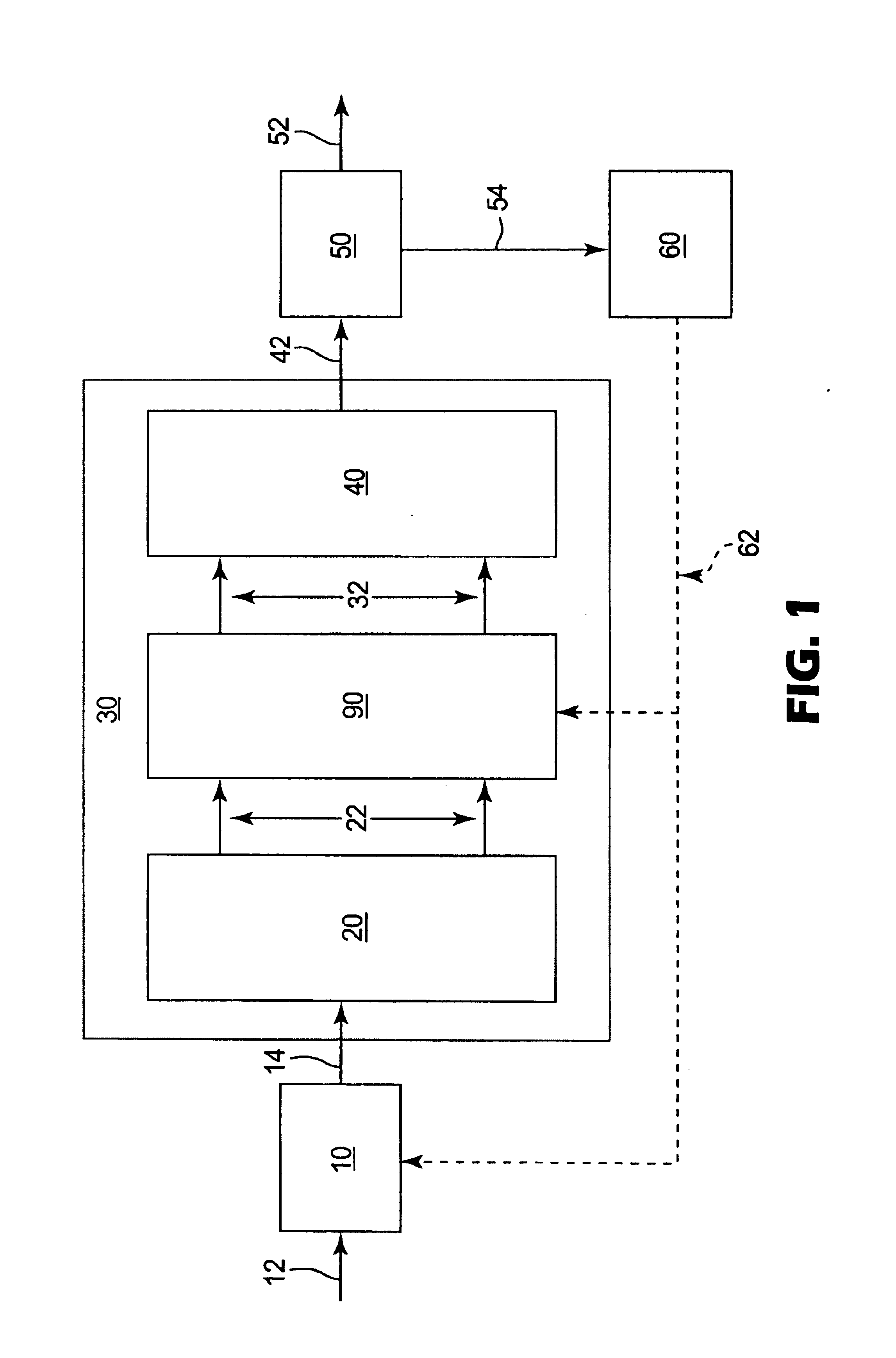
[0034]The present invention is directed to a method for compensation and a system for compensation for polarization mode dispersion (PMD). FIG. 1 illustrates a component flow diagram of a method for compensating for polarization mode dispersion of an incoming optical communications signal 12. A polarization controller 10, that adjusts the state of polarization to minimize the distortion of the signal, receives the incoming signal 12. The output 14 of the polarization controller 10 is optically coupled and aligned to a differential polarization delay unit 30, which includes a polarization splitter 20, a differential delay line 90 and a polarization combiner 40. The polarization splitter 20 receives the output 14 and splits the communication signal into a first and a second orthogonal state of polarization 22. The polarization states 22 are directed into the differential delay line 90 that compensates for PMD by delaying the “fast” component of polarization with respect to the “slow” ...


PUM


Abstract

A method for compensating for polarization mode dispersion of an incoming optical communications signal including the step of orienting the state of polarization of the incoming optical communications signal with respect to the axes of a polarization splitter. The communications signal is split into a first and a second orthogonal states of polarization at a split point. The first of the polarization states is directed to a first birefringent optical waveguide having a first chirped grating having a first reference reflection point. The second of the polarization states is directed to a second birefringent optical waveguide having a second chirped grating having a chirp pattern substantially similar to that of the first chirped grating and having a second reference reflection point. The optical path length from the second reflection point to the split point is adjustably varied to compensate for polarization dispersion between the first and second states of polarization. The first and second polarization states are then recombined into an output signal.

Description

RELATED APPLICATIONS[0001]The present application Ser. No. 10 / 036,987 is related to the co-pending, commonly assigned application entitled, “System for All Order Dispersion Compensation”, Applicants' filed co-currently with the present application, which is hereby incorporated by reference.BACKGROUND OF THE INVENTION[0002]The present invention relates to a method and system for polarization mode dispersion compensation of optical signals. In particular, the present invention relates to a method for polarization mode dispersion compensation using at least two linearly chirped Bragg gratings to selectively tune the reflection points of two polarization resolved signals, creating a variable polarization dependent delay.[0003]Present day telecommunication systems require that optical signals be conveyed over very long distances. In an optical communications signal, data are sent in a series of optical pulses. Real signal pulses are composed of a distribution of wavelengths and polarizat...

Claims


Application Information

Patent Timeline
Patent Type & Authority Patents(United States)
IPC IPC(8): G02B6/34H04B10/18H04B10/2569
CPCG02B6/278H04B10/2569G02B6/2932
Inventor KOCH, BARRY J.SMITH, TERRY L.DEBAUN, BARBARA A.
Owner PROXIMON FIBER SYST
Why Eureka
Try Eureka