Support volume calculation for a CAD model

a support volume and cad model technology, applied in the field of solid freeform fabrication, can solve the problems of unsatisfactory support function, unsatisfactory support function, unsolidified material not available to perform the desired support function, etc., to achieve rapid and accurate prediction, rapid and accurate prediction of the volume and weight of the support material, and rapid and accurate prediction

Inactive Publication Date: 2005-06-14
3D SYST INC
View PDF19 Cites 74 Cited by
  • Summary
  • Abstract
  • Description
  • Claims
  • Application Information

AI Technical Summary

Benefits of technology

[0017]It is a further aspect of this invention to provide such a method that is both accurate and rapid.
[0018]The invention includes in a solid freeform fabrication process wherein an object is formed with a removable support material, the process including the steps of a) rapidly and accurately predicting the volume and weight of support material required to form the object prior to commencing the building of the object, b) predicting when replenishment of the support material is required, and c) tracking consumption of support material over time.
[0019]Further the invention includes in a solid freeform fabrication process wherein an object is formed with a removable support material,

Problems solved by technology

However, since the third approach, SDM, does not necessarily supply a working surface, it suffers from a particularly acute problem of accurately forming and placing subsequent lamina which contain regions not fully supported by previously dispensed material such as regions including outward facing surfaces of the object in the direction of the previously dispensed material.
In the typical building process where subsequent laminae are placed above previously formed laminae this is particularly a problem for down-facing surfaces (down-facing portions of laminae) of the object.
Thus, nothing will be available to provide a working surface for or to support any down-facing surfaces appearing on a subsequent cross-section.
ly. The previous lamina is non-existent in down-facing regions and is thus unavailab

Method used


Image

  • Support volume calculation for a CAD model
  • Support volume calculation for a CAD model
  • Support volume calculation for a CAD model

Examples


Embodiment Construction

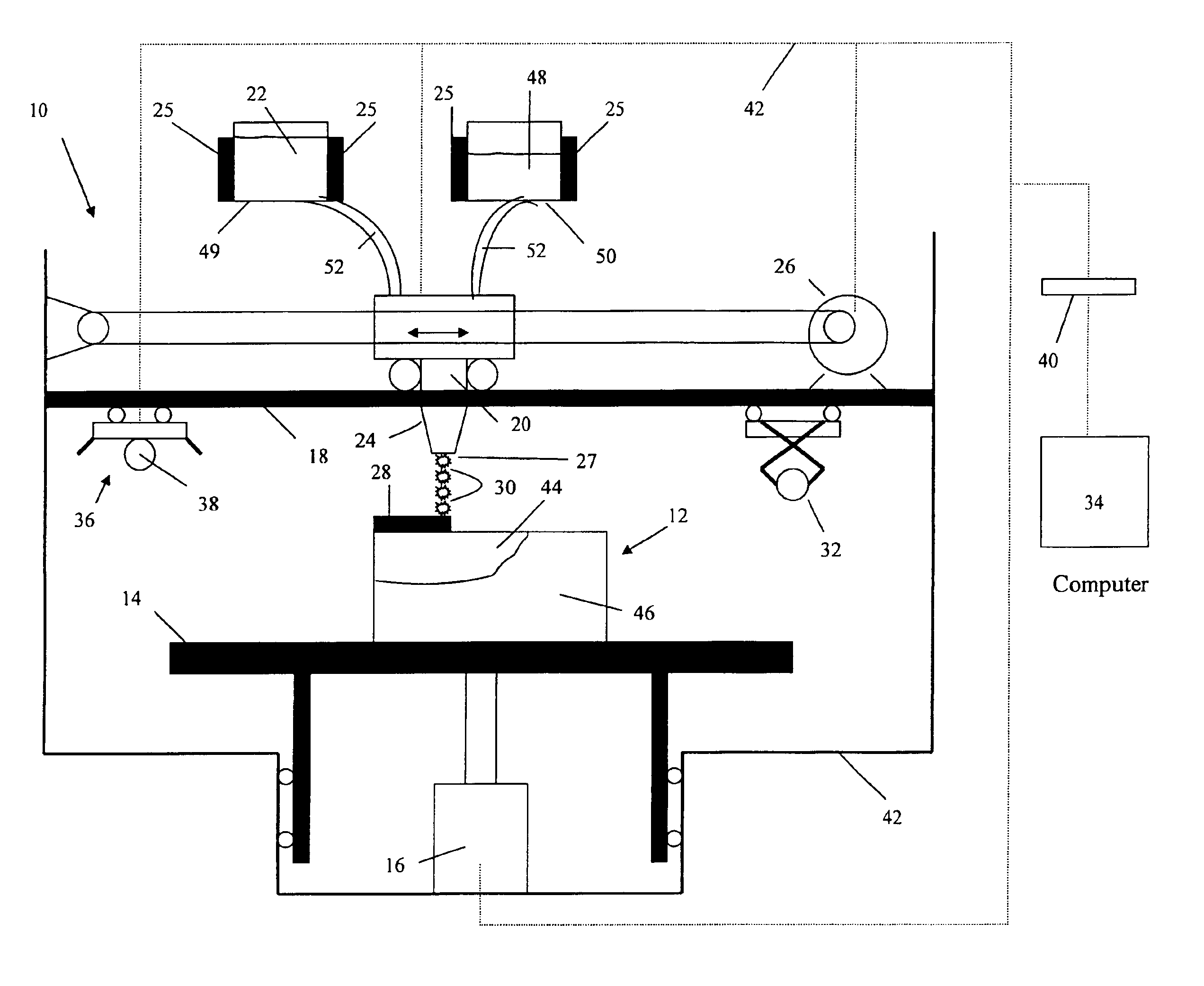
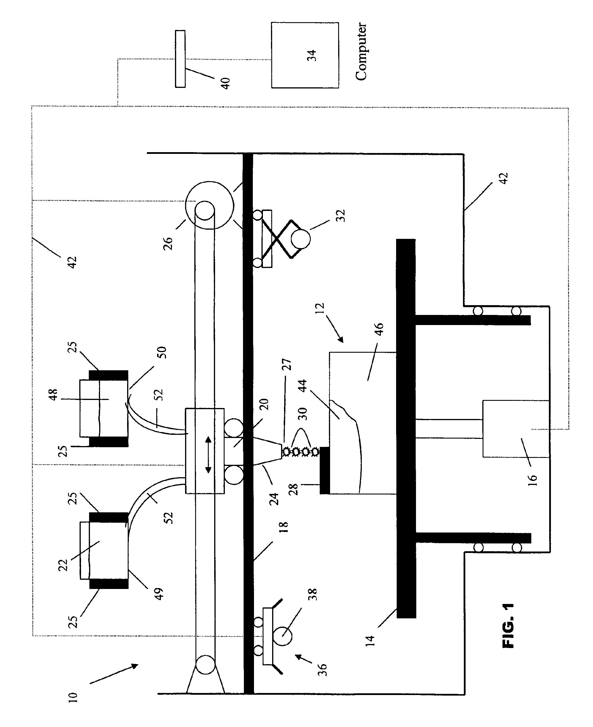
[0033]While the present invention is applicable to many SFF techniques the invention will be described with respect to a SDM technique utilizing an ink jet print head dispensing a ultraviolet radiation curable phase change material. However it is to be appreciated that the present invention can be implemented with any SFF technique utilizing a wide variety of materials. For example, the curable phase change material can be cured by exposure to actinic radiation having wavelengths other than in the ultraviolet band of the spectrum, or by subjecting the material to thermal heat. Or the curing may be affected by a selective exposure from a laser beam, as in stereolithography. Alternately the build material may not be a curable material but a material which changes phase due to temperature, being deposited in a molten state, and quickly hardening due to cooling.

[0034]Referring particularly to FIG. 1 there is illustrated generally by the numeral 10 a SDM apparatus for practicing an embod...


PUM

PropertyMeasurementUnit
Lengthaaaaaaaaaa
Lengthaaaaaaaaaa
Lengthaaaaaaaaaa

Abstract

In solid freeform fabrication processes that make use of a removable support material, pre-calculation of the amount of support material needed for a build is difficult (inaccurate or slow) because the digital data for generating the support material is often not generated until the build is in progress. A method is proposed that has been shown to generate rapid and accurate estimates of the amount of both build and support material needed before a build begins, to accurately predict before a build begins when replenishment materials are needed, and to track material consumptions over time.

Description

[0001]This application is a continuation-in-part of application Ser. No. 10 / 188,574 filed Jul. 2, 2002 now abandoned.BACKGROUND OF THE INVENTION[0002]1. Field of the Invention[0003]The invention relates in general to solid freeform fabrication, and in particular to those solid freeform fabrication techniques that build objects in a layer-wise fashion and require a support structure for the build. This can include stereolithography, selective deposition modeling, and direct composite manufacturing using pastes or semi-solid materials.[0004]2. Description of the Prior Art[0005]Several technologies have been developed for the rapid creation of models, prototypes, and parts for limited run manufacturing. These technologies are generally called Solid Freeform Fabrication techniques, and are herein referred to as “SFF”. Some SFF techniques include stereolithography, selective deposition modeling, laminated object manufacturing, selective phase area deposition, multi-phase jet solidificati...

Claims


Application Information

Patent Timeline
IPC IPC(8): G06F19/00G05B19/4099
CPCG05B19/4099B29C67/0051G05B2219/49016G05B2219/49013G05B2219/35162B29C2035/0283G05B2219/49038B29C64/106B33Y30/00B33Y40/20B33Y50/02
Inventor CHEN, YONGKULKARNI, RAJEEV B.
Owner 3D SYST INC
Why Eureka
Try Eureka