
Variable radii cutter

a cutter and radii technology, applied in the field of universal cutting tools, can solve the problems of time-consuming and frustrating, ruins the tool bit, and consuming tim

Inactive Publication Date: 2005-06-21
TRAN HIEP N +1
View PDF14 Cites 7 Cited by
  • Summary
  • Abstract
  • Description
  • Claims
  • Application Information

AI Technical Summary

Benefits of technology

[0006]It is therefore an object of this invention to provide a single cutting tool in the form of a variable radii cutter which avoids the aforementioned machining operation problems associated with the use of conventional cutting tool bits.
[0010]It is a further object of this invention to provide a variable radii cutter which may be manufactured from readily available materials by conventional manufacturing processes.
[0011]It is a still a further object of this invention to provide a variable radii cutter that is simple in design, simple to manufacture, low in cost and fun to use.
[0012]This invention results from the realization that there is a great need for a variable radii cutter that can conveniently and effortlessly cut various sizes of radii on a workpiece without having to frequently change the cutter. The resulting invention provides a user the capability of conveniently and efficiently being able to rapidly fabricate a part with a single tool, thereby saving time and money.
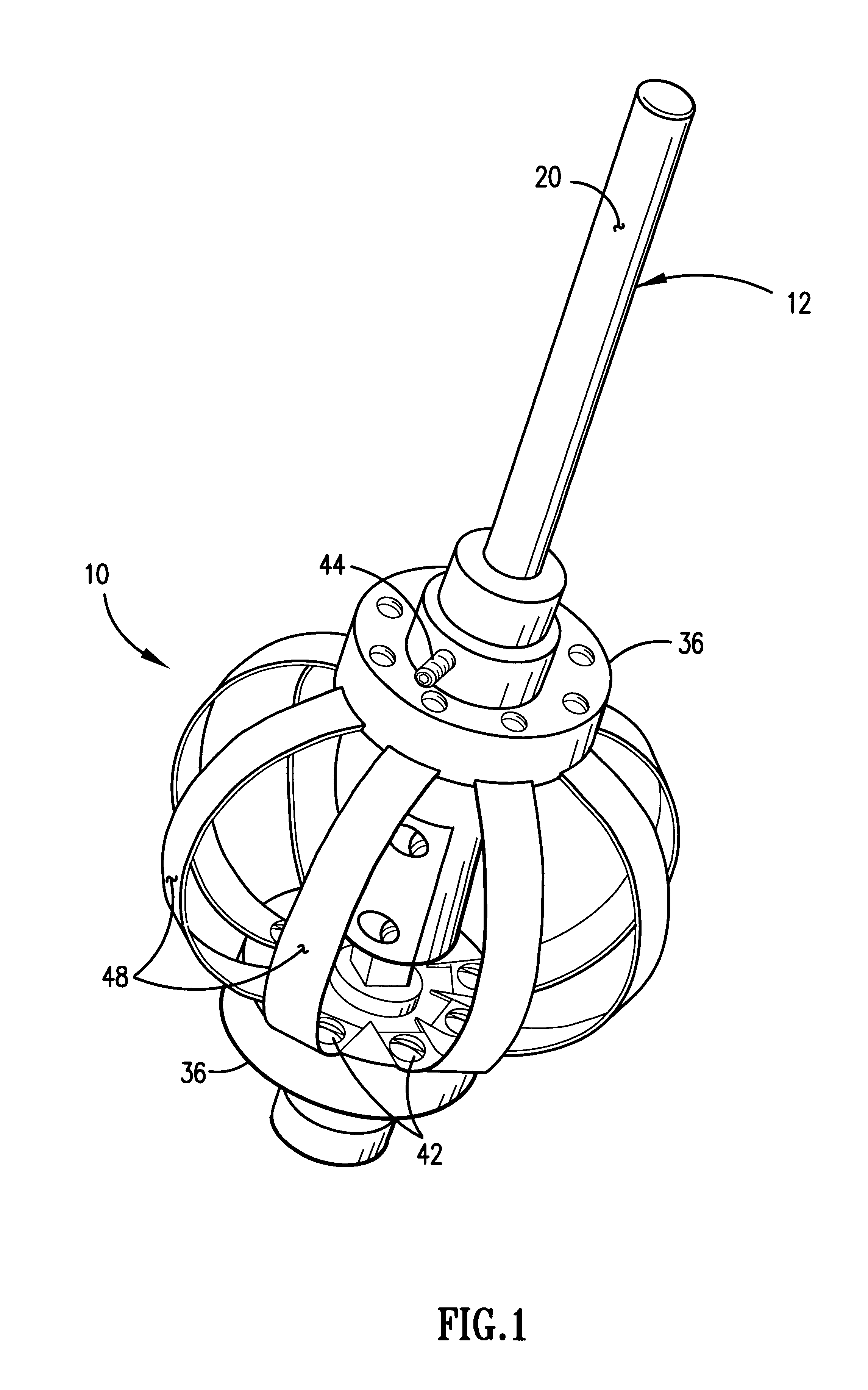
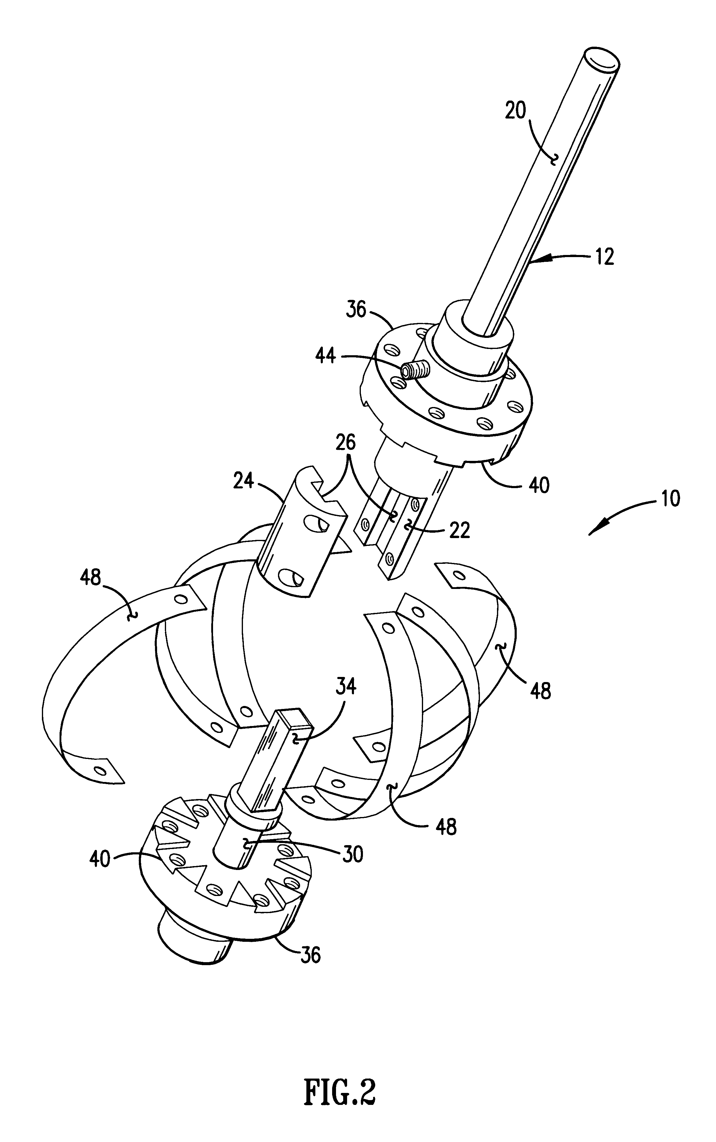
[0013]The above and the other objects are achieved in accordance with the present invention, which, according to a first aspect, provides a variable radii cutter comprising a shaft having an upper portion slideably coupled to a lower portion; a spindle disposed in an opposed spaced relationship on the upper portion and on the lower portion of the shaft; a cutter means disposed between the spindle and about the shaft and the cutter means removably attachable thereto the spindle and means for varying a radius of the cutter means so that various radii may be cut on a workpiece with the variable radii cutter.
[0016]The fourth aspect is a method for cutting various sizes of radii on a workpiece with a variable radii cutter without a need to replace the variable radii cutter for each profile cut on the workpiece.

Problems solved by technology

A problem with such traditional tools is that most machined parts have varying contours such as a changing radius on the edge concave, a fillet at a corner, multiple radii and other rapidly changing features which require a machinist to find and then to frequently exchange the tool bit with an appropriate one to form the final shape of the part.
This is time consuming and frustrating particularly when the machinist must search through dozens of tool bits until the correct one is located.
Furthermore, if a particular tool bit is unsuitable for the cutting task, the machinist oftentimes grinds and machines the tool bit in an attempt to simulate the desired radii to be cut.
This, too, is time consuming and ruins the tool bit as well as compromising the accuracy of the workpiece.

Method used


Image

  • Variable radii cutter
  • Variable radii cutter
  • Variable radii cutter

Examples


example

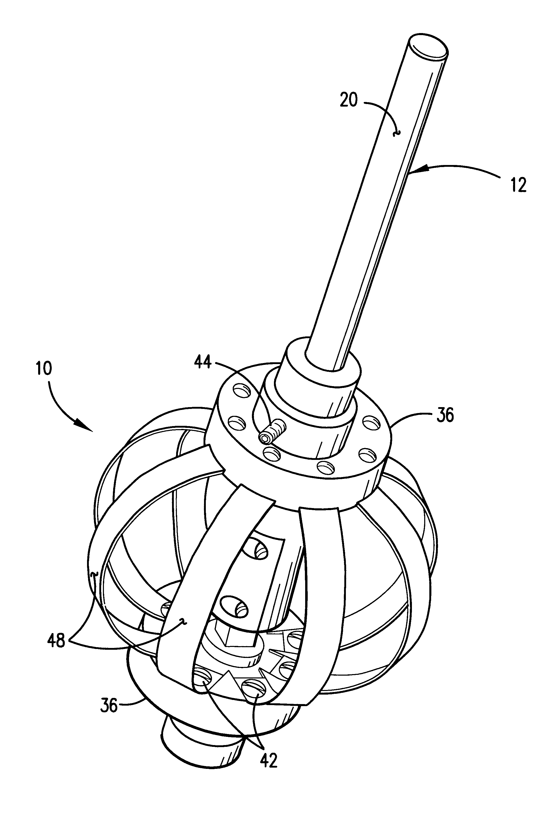
[0038]The variable radii cutter 10 was actually reduced to practice according to the teachings of this invention. A prototype was made and tested with good results while automatically cutting workpieces made of foam, wax, wood and metal. The prototype utilized a cutter means in the form of eight (8) hardened spring steel blades connected to a pair of spindles attached to a shaft at an upper portion and at a lower portion. The blades were fabricated from standard 32 gage flat stock spring steel and were machined to about 0.25 inch (0.06 cm) wide and 2.68 inch (6.8 cm) long. The number of blades chosen included consideration for proper rotational inertia balance for mounting on the milled guide means in the form of a groove on the spindle. The blades were removably attachable with threaded fasteners passing through holes in the blades and into the corresponding tapped holes in the spindle. The blades, spindle and the shaft were made from stainless steel. The variable radii cutter 10 u...


PUM

PropertyMeasurementUnit
Sizeaaaaaaaaaa
Radiusaaaaaaaaaa

Abstract

A variable radii cutter which eliminates the need for having to provide a wide assortment of cutting tool bits for continuously imparting various sizes of radii on a workpiece is disclosed. In one embodiment, the variable radii cutter has a cutter in the form of a plurality of blades which mechanically expand and contract in response to one of an automated adjustment mechanism and a manual adjustment for accommodating various sizes of radii. In another embodiment, a ball made of rubber having an abrasive disposed thereon is used as the cutter and operates in the same manner as described above.

Description

FIELD OF THE INVENTION[0001]This invention relates generally to a cutting apparatus. More particularly, the present invention relates to a universal cutting tool in the form of a variable radii cutter that cuts various sizes of radii on a workpiece by mechanically adjusting the size of the cutter for the particular radii to be cut without the need for tool bit changes.BACKGROUND OF THE INVENTION[0002]Typical machining operations such as milling and routing utilize specially designed tool bits that have a fixed radii cutting feature thereon. A problem with such traditional tools is that most machined parts have varying contours such as a changing radius on the edge concave, a fillet at a corner, multiple radii and other rapidly changing features which require a machinist to find and then to frequently exchange the tool bit with an appropriate one to form the final shape of the part. This is time consuming and frustrating particularly when the machinist must search through dozens of t...

Claims


Application Information

Patent Timeline
IPC IPC(8): B23C5/00B23C3/12B24D13/12B26D3/06B27G13/00B27G13/12
CPCB23C3/12B23C5/00B24D13/12B26D3/06B27G13/12B27G13/00B23C2260/04Y10T408/858Y10T409/309408Y10T408/8588Y10T409/30952
Inventor TRAN, HIEP N.DOUMANIDIS, HARIS
Owner TRAN HIEP N
Learn More