Pressure control method and processing device

a processing device and pressure control technology, applied in fluid pressure control, electric discharge tubes, instruments, etc., can solve the problems of inconsistency in processing, difficult to obtain pressure data that reflect a drastic pressure change, and increase the length of time required for arithmetic processing

Inactive Publication Date: 2005-06-21
TOKYO ELECTRON LTD
View PDF7 Cites 2 Cited by
  • Summary
  • Abstract
  • Description
  • Claims
  • Application Information

AI Technical Summary

Benefits of technology

[0021]In addition, the present invention provides a plasma processing device that is characterized in that the pressure inside the process chamber is controlled by adopting the pressure control method with the outstanding advantages described above.

Problems solved by technology

As a result, it is difficult to obtain pressure data that reflect a drastic pressure change since the selection of the appropriate pressure sensor cannot be made promptly when the pressure inside the process chamber changes greatly.
Thus, a problem arises in that the resulting delay in the control on the pressure inside the process chamber tends to cause inconsistency in the processing.
However, if the detected pressure is finely analyzed over a pressure range that does not affect the processing, too, the length of time required for the arithmetic processing increases.
This may lead to a problem in that the response of the pressure control valve becomes poor.

Method used


Image

  • Pressure control method and processing device
  • Pressure control method and processing device
  • Pressure control method and processing device

Examples


Embodiment Construction

[0024]The following is a detailed explanation of a preferred embodiment achieved by adopting the pressure control method according to the present invention in a pressure control method implemented in conjunction with a plasma etching device, given in reference to the attached drawings.

(1) Structure of the Etching Device

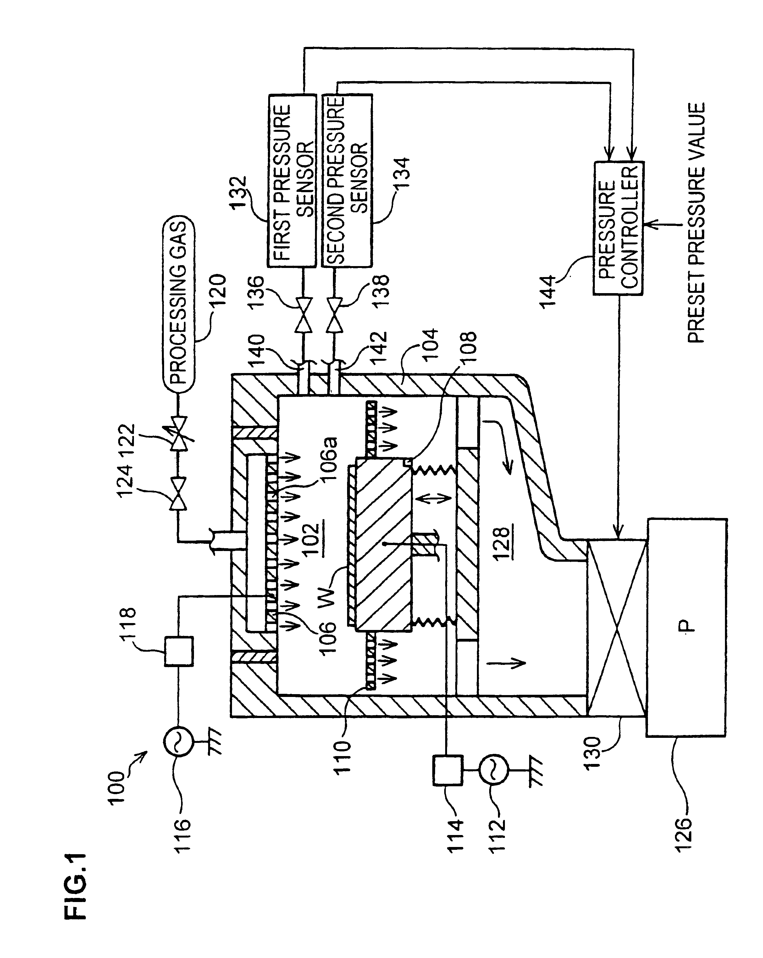
[0025]First, in reference to FIG. 1, the structure of an etching device 100 in which the present invention may be adopted is explained. A process chamber 102 is formed inside an electrically conductive airtight processing container 104. The processing container 104 is grounded for safety. In addition, an upper electrode 106 and a lower electrode 108 are provided facing opposite each other inside the process chamber 102. The lower electrode 108 is also utilized as a stage on which a workpiece such as a semiconductor wafer (hereafter referred to as the “wafer”) W is placed. A diffusion plate 110 is provided around the lower electrode 108. A high frequency power supply 1...


PUM


Abstract

First and second pressure sensors 132 and 134 that perform pressure detection over different pressure detection ranges from each other detect the pressure within a process chamber 102 of an etching device 100. A pressure controller 144 selects optimal pressure data in correspondence to the pressure inside the process chamber from the pressure data provided by the first and second pressure sensors 132 and 134. It also analyzes the selected pressure data at a resolution selected in correspondence to the pressure inside the process chamber 102 and thus obtains pressure data achieving a predetermined data density. The pressure controller 134 controls a pressure control valve 130 so as to ensure that the pressure data match preset pressure data.

Description

TECHNICAL FIELD[0001]The present invention relates to a pressure control method and a plasma processing device, and more specifically, it relates to a pressure control method adopted in a means for pressure control provided in a semiconductor manufacturing device.BACKGROUND ART[0002]A plasma processing device such as a plasma etching device, which is capable of performing various types of plasma processing, is utilized during a semiconductor device manufacturing process in the related art. Such a device processes a workpiece placed within a process chamber by generating plasma inside the process chamber with the pressure of its atmosphere sustained at a level lowered to a preset level. In addition, the pressure inside the process chamber is adjusted by controlling a pressure (evacuation quantity) control valve based upon pressure data provided by a pressure sensor.[0003]As ultra high integration and super multi-layer structures are becoming increasingly common in semiconductor devic...

Claims


Application Information

Patent Timeline
Patent Type & Authority Patents(United States)
IPC IPC(8): H01J37/32H01L21/00G05D16/00H01L21/302H01L21/205H01L21/3065
CPCH01J37/32449H01L21/67253H01J37/3299H01J37/32935
Inventor HIROSE, EIJIIWABUCHI, NORIYUKIYOKOUCHI, TAKESHISUZUKI, SHINGO
Owner TOKYO ELECTRON LTD
Why Eureka
Try Eureka