Water purifying apparatus
a technology of water purification apparatus and water filter, which is applied in the direction of filtration separation, separation process, instruments, etc., can solve the problems of complex configuration and large apparatus, complex apparatus and large apparatus, etc., and achieve the effect of controlling the operation of the display uni
- Summary
- Abstract
- Description
- Claims
- Application Information
AI Technical Summary
Benefits of technology
Problems solved by technology
Method used
Image

Examples
first embodiment
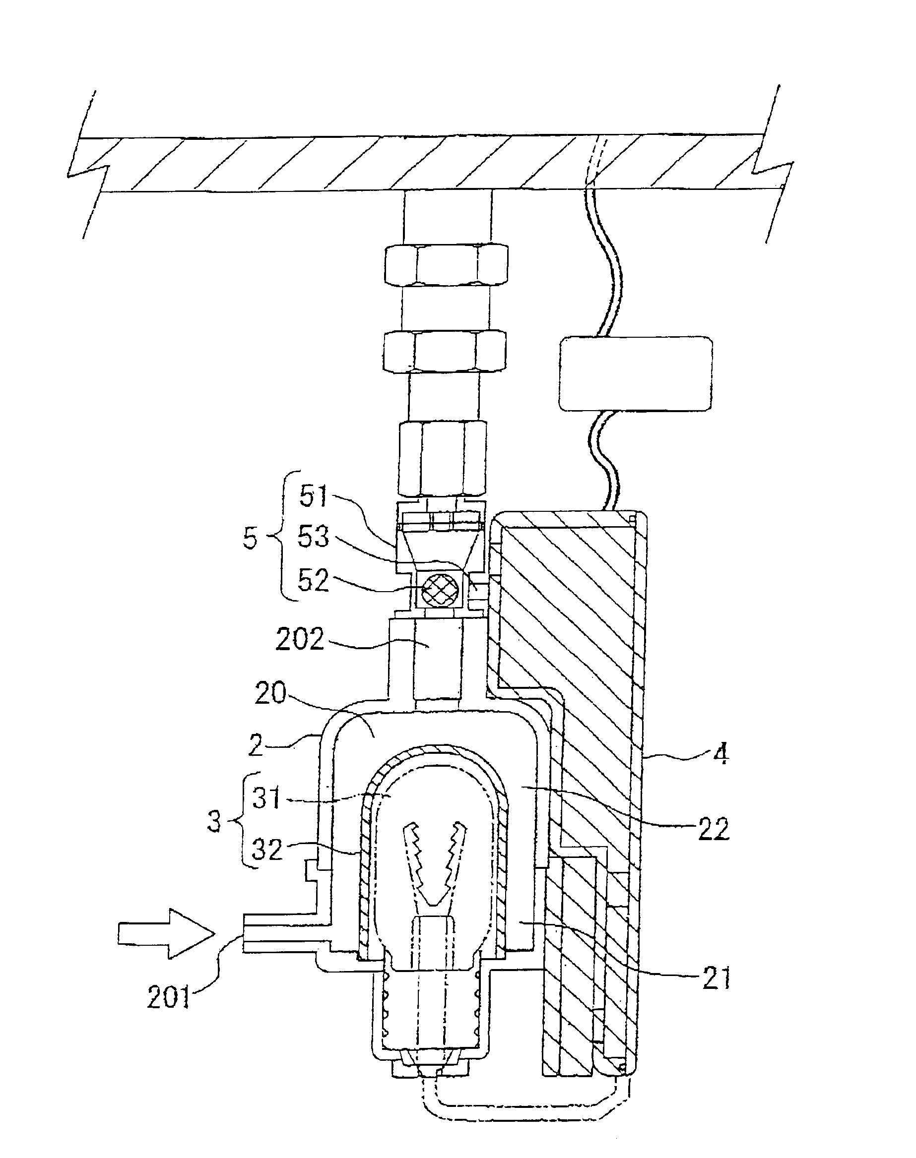
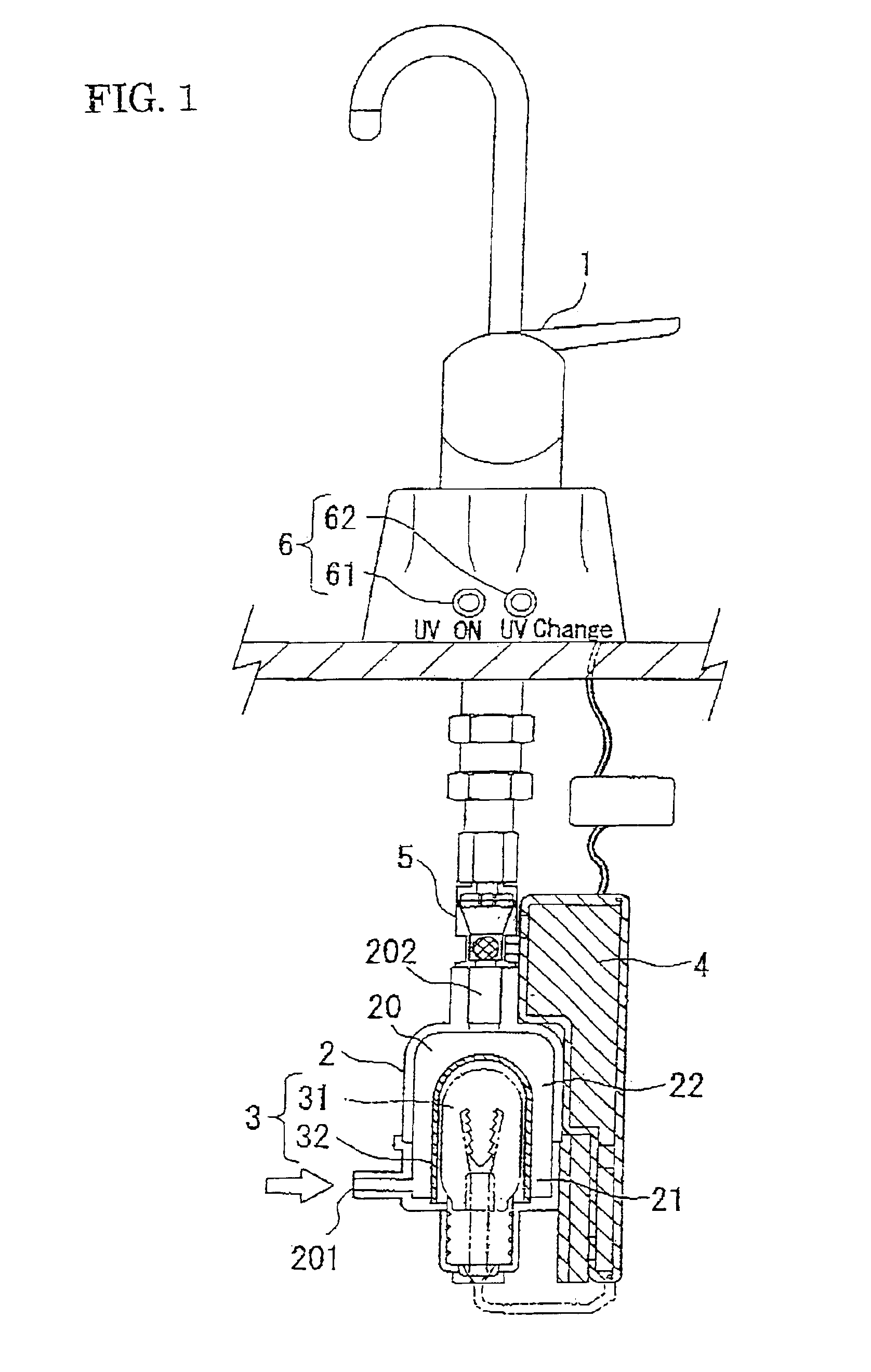
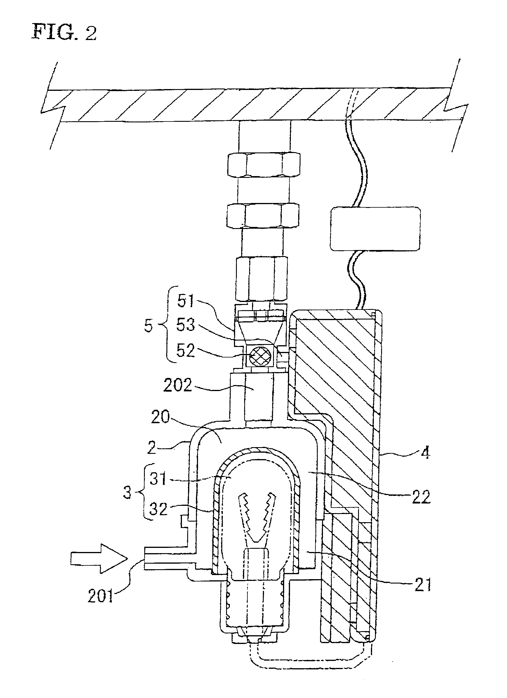
[0028]The following is a description based on FIG. 1 and FIG. 2 of a purifying apparatus of the present invention. This purification device is a purification device for purifying water being sent out of a faucet 1. Here, water may be arbitrary water such as tap water, well water, or river water, etc. The purifying apparatus of this embodiment comprises a main body 2, ultraviolet light generator 3, control unit 4, detection means 5, and display unit 6.
[0029]The main body 2 is equipped with a passage 20 allowing water to pass provided within. An inflow port 201 of the passage 20 is connected to a water supply side (for example, mains water piping or output side piping of a pump sending water out). An outlet port 202 of the passage 20 is connected to the side of the faucet 1 via a guide 51 (described later) of detection means 5 and a well-known connector. Of course, the outlet port 202 may also be directly connected to the faucet 1. The main body 2 may be configured from a single body,...
third embodiment
[0044]Next, a description is given based on FIG. 5 and FIG. 6 of a purifying apparatus of the present invention. In this embodiment, a display unit 260 is used in place of the display unit 6 (refer to FIG. 5). A display displaying the lifespan of the ultraviolet lamp 31 and the lifespan of the filter 9 (refer to FIG. 5) used on the upstream side of the passage 20 as a string of numerals can be used as the display unit 260. This display is, for example, a liquid crystal display. The lifespan of the filter 9 can be ascertained, for example, as follows. Namely, a phototransistor 10a and an infra-red LED 10b are arranged facing each other on the upstream side of the filter 9, with the lifespan being estimated at the control unit 4 based on the extent to which water detected in this manner is polluted. Further, in this embodiment, if the changing period for the filter 9 arrives, the LED 263 taken as part of the display unit 6 is made to light up.
[0045]Remaining configuration and operatio...
fourth embodiment
[0048]Next, a description is given with reference to FIG. 7 of a water purifying apparatus of the present invention. In this embodiment, a filament-type lamp is used as the ultraviolet lamp 31. It is appropriate to employ a lamp with, for example, an output in the order of 18 to 20 W with output light including wavelength components in the vicinity of 275 nm as the filament-type ultra-violet lamp. An example configuration for this kind of lamp is shown below.
[0049]Filament: Tungsten (enclosed within a glass tube)
[0050]Ultraviolet Light Generating Source: Plate applied with mercury amalgam (enclosed within a glass tube)
[0051]Glass tube material: Ultraviolet light-transmitting glass (for example, an arbitrary glass such as borosilicated glass 9741 etc. by Corning Incorporated).
[0052]Lamp drive voltage: approximately 12V.
[0053]Further, in the first embodiment the movable member 52 of the detection means 5 is taken to be a ball-shape but in the fourth embodiment, a plug-shaped moveable ...
PUM
| Property | Measurement | Unit |
|---|---|---|
| Time | aaaaa | aaaaa |
| Pressure | aaaaa | aaaaa |
| Flow rate | aaaaa | aaaaa |
Abstract
Description
Claims
Application Information
 - R&D Engineer
- R&D Manager
- IP Professional
- Industry Leading Data Capabilities
- Powerful AI technology
- Patent DNA Extraction
Browse by: Latest US Patents, China's latest patents, Technical Efficacy Thesaurus, Application Domain, Technology Topic.
© 2024 PatSnap. All rights reserved.Legal|Privacy policy|Modern Slavery Act Transparency Statement|Sitemap