Control device of a position control motor

a control device and position control technology, applied in the direction of electric programme control, electronic commutator, dynamo-electric converter control, etc., can solve the problems of increasing the amount of heat generated by the motor, and increasing the cost of operation. , to achieve the effect of good energy efficiency, good responsiveness and reduced generation of heat from the motor

Active Publication Date: 2005-06-21
ORIENTAL MOTOR
View PDF12 Cites 13 Cited by
  • Summary
  • Abstract
  • Description
  • Claims
  • Application Information

AI Technical Summary

Benefits of technology

[0024]Also, since current is supplied to the motor windings according to the load applied to the motor, the energy efficiency is good and the generation of heat from the motor is reduced.
[0025]Furthermore, because the θ-T characteristics of the control with the first control portion can be used directly, there is no control delay and as such the

Problems solved by technology

Conventionally, how to prevent step out of the motor was a very important issue in the control of such brushless motors and stepping motors.
At present it has become increasingly less practical (see Japanese Patent No. 2562874, for example).
However, when the rotation angle exceeds ±1.8° (±90° electrical angle), the problem of step down, in which torque that is generated is reduced or invert

Method used


Image

  • Control device of a position control motor
  • Control device of a position control motor
  • Control device of a position control motor

Examples


Embodiment Construction

[0036]Preferred embodiments of the present invention are illustrated below in detail with reference to the drawings.

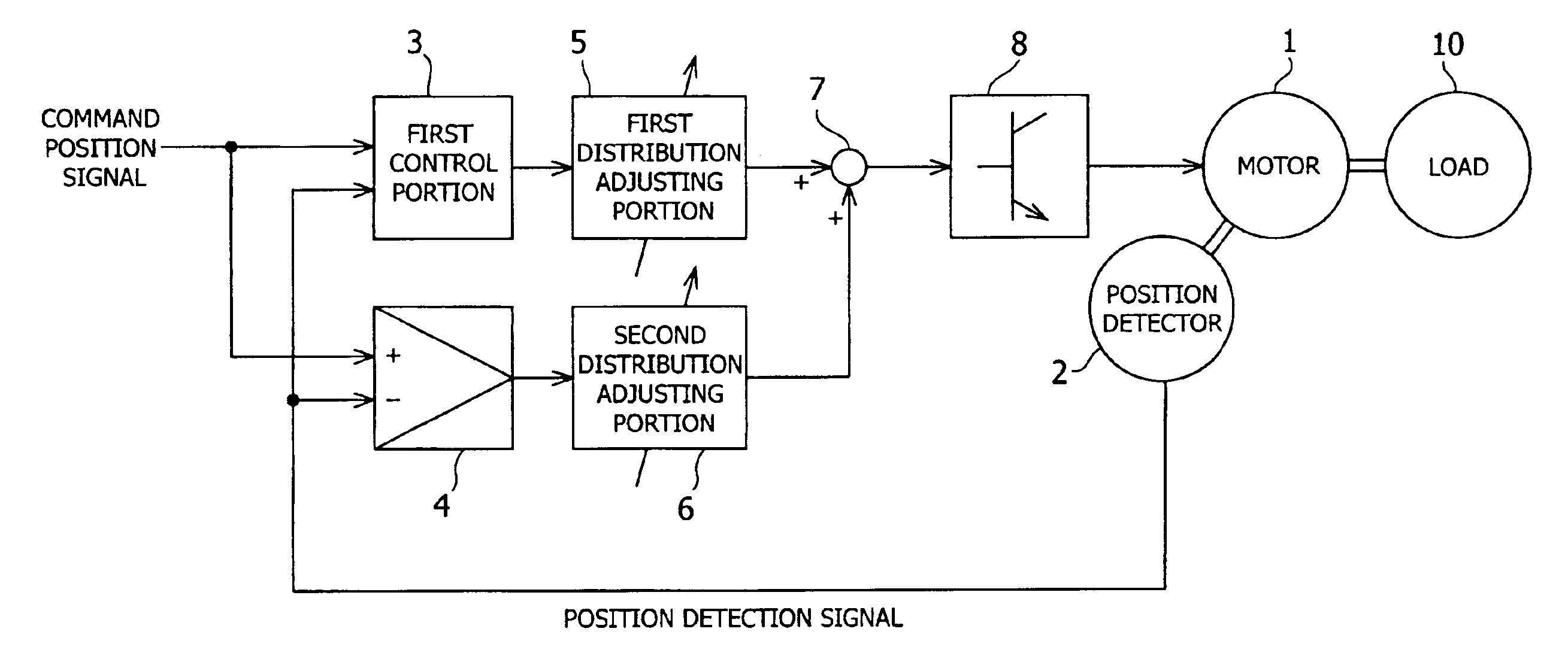
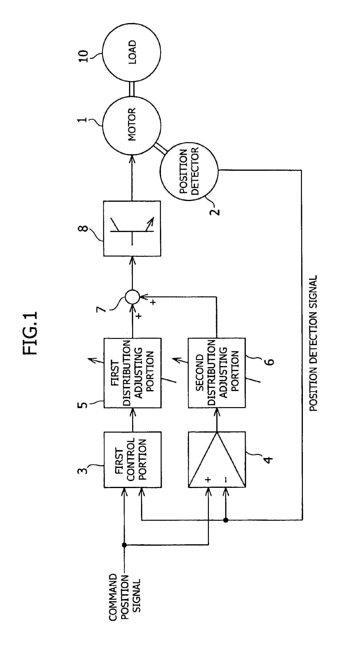
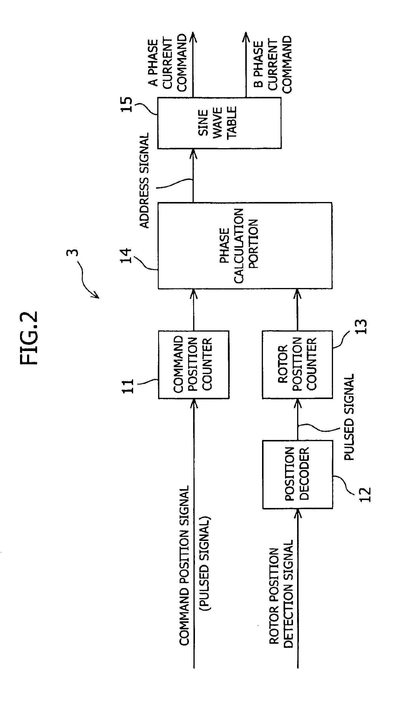
[0037]FIG. 1 is a block diagram showing an embodiment of the control device of the position control motor according to the present invention, FIG. 2 is a block diagram showing an example of the inside of the first control portion of the control device, and FIG. 3 is a block diagram of the servo control portion of the second control portion of the control device.

[0038]In FIG. 1, reference numeral 1 denotes a two-phase hybrid stepping motor, in which 50 rotor teeth are formed on the outer circumferential surface of its rotor in opposition to stator teeth formed on the inner circumferential surface of the stator of the motor 1. A position detector 2 is linked to the rotor of the motor 1, and a position detection signal from the position detector 2 is input to first and second control portions 3 and 4 as a feedback quantity. A load 10 is mechanically applied to the motor 1...


PUM


Abstract

The present invention provides a control device of a position control motor for preventing step out of the position control motor, wherein the heat generated by the position control motor is small and the energy efficiency is good. The device is constituted by a detection portion 2 detecting the rotor position of a position control motor 1, first and second control portions 3 and 4 outputting signals corresponding to a current to be supplied to the motor winding based on the deviation between the position detection signal and a command position signal, first and second distribution adjusting portions 5 and 6 distributing the output signals of the first and second control portions 3 and 4, a signal synthesis portion 7 synthesizing by vector addition the output signals distributed by the first and second distribution adjusting portions 5 and 6, and an amplification portion 8 outputting the synthesized output signal to the motor winding, and the device controls the position of the motor with the command position signal. The first control portion 3 monitors the deviation between the command position and the rotor position that is detected, and based on the amount of this deviation (electrical angle), switches to one of two modes, preventing step down.

Description

FIELD OF THE INVENTION AND RELATED ART STATEMENT[0001]The present invention relates to a control device for a position control motor such as brushless motors and stepping motors, and more particularly relates to a control device for a position control motor that increases and decreases the current flowing to the motor winding of the position control motor in accordance with the load torque acting on that position control motor.[0002]Conventionally, how to prevent step out of the motor was a very important issue in the control of such brushless motors and stepping motors. The principle of step out is discussed later.[0003]As regards a control device of a stepping motor having a function for preventing this step out, there is for example the invention of a drive control for preventing step out of a stepping motor that has already been proposed by the inventors of the present application, and at the time that this proposal was made it was extremely effective. At present it has become i...

Claims


Application Information

Patent Timeline
IPC IPC(8): H02P8/42H02P8/14H02P8/16H02P6/06H02P6/08H02P6/15H02P8/00H02P8/38
CPCH02P8/42H02P8/16Y02P80/10
Inventor ITABASHI, MASANARI
Owner ORIENTAL MOTOR
Why Eureka
Try Eureka