Image processing apparatus and method, and its computer program and storage medium

a technology of image processing and data, which is applied in the field of image processing apparatus and method for encoding/decoding data, and its computer program and storage medium, and can solve problems such as complex sync process and data management, and complex managemen

Inactive Publication Date: 2005-06-21
CANON KK
View PDF5 Cites 53 Cited by
  • Summary
  • Abstract
  • Description
  • Claims
  • Application Information

AI Technical Summary

Benefits of technology

[0039]According to one aspect of the present invention, the apparatus comprises shape information change means for changing shape information to expand on the basis of

Problems solved by technology

When meta information, copyright information, or the like is to be appended in JPEG2000, such information must be separately appended in addition to JPEG2000 encoded data, resulting in

Method used


Image

  • Image processing apparatus and method, and its computer program and storage medium
  • Image processing apparatus and method, and its computer program and storage medium
  • Image processing apparatus and method, and its computer program and storage medium

Examples


first embodiment

[First Embodiment]

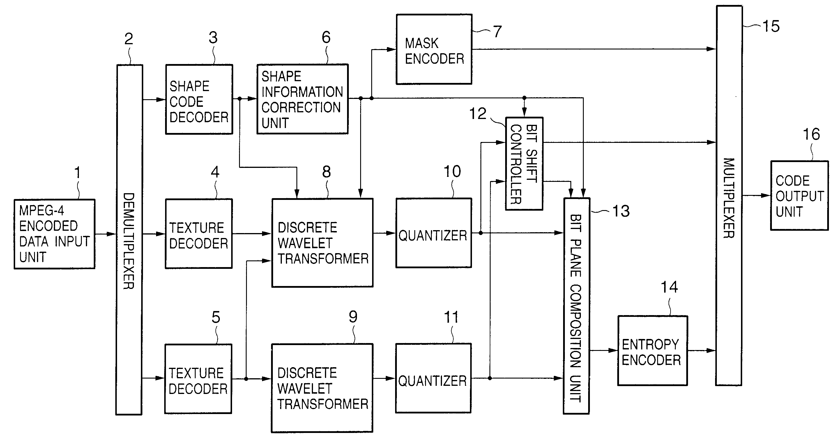
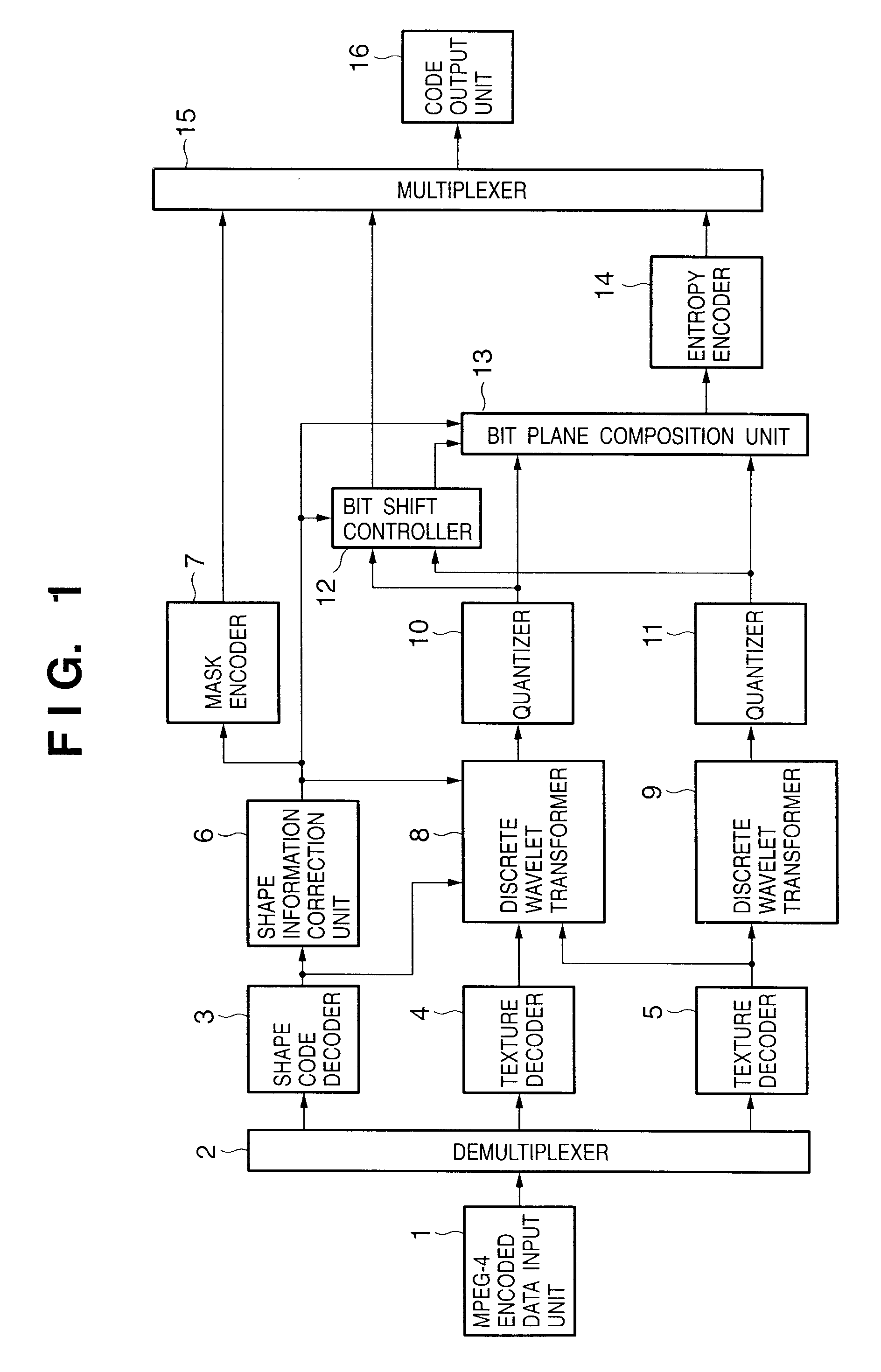
[0078]FIG. 1 is a block diagram showing the arrangement of an image processing apparatus according to the first embodiment of the present invention. Note that this embodiment will explain a case wherein MPEG-4 encoded data is input and encoded, and encoded data similar to JPEG2000 encoded data is output.

[0079]Referring to FIG. 1, reference numeral 1 denotes an MPEG-4 encoded data input unit for inputting MPEG-4 encoded data. Reference numeral 2 denotes a demultiplexer for demultiplexing input MPEG-4 encoded data, and inputting demultiplexed data to respective units. Reference numeral 3 denotes a shape code decoder for receiving and decoding shape encoded data of an object, which is encoded by MPEG-4 and is demultiplexed by the demultiplexer 2. Reference numeral 4 denotes a texture decoder for decoding the texture of an object demultiplexed by the demultiplexer 2. Reference numeral 5 denotes a texture decoder for decoding the texture of encoded data of a background ...

second embodiment

[Second Embodiment]

[0098]FIG. 4 is a block diagram showing the arrangement of an image processing apparatus according to the second embodiment of the present invention. Note that the same reference numerals denote the same building components as those in the first embodiment, and a detailed description thereof will be omitted. The second embodiment will exemplify a case wherein image data sensed by cameras 31 and 32 are input, and are encoded and output.

[0099]Referring to FIG. 4, reference numerals 31 and 32 denote cameras for sensing an image and generating video signals. Reference numeral 33 denotes an object extraction unit for extracting an object from the captured video signal in accordance with a known algorithm. For example, extraction is attained by, e.g., chroma-key. Reference numeral 34 denotes a frame memory for holding image data captured by the camera 32.

[0100]Image data captured by the camera 31 is input to the object extraction unit 33 in units of frames. The object e...

third embodiment

[Third Embodiment]

[0106]FIG. 5 is a block diagram showing the arrangement of an image processing apparatus according to the third embodiment of the present invention. The third embodiment will explain a case wherein JPEG2000 encoded data generated in the first embodiment is input, and MPEG-4 encoded data is output.

[0107]Referring to FIG. 5, reference numeral 51 denotes a code input unit for receiving JPEG2000 encoded data generated according to the first embodiment. Reference numeral 52 denotes a demultiplexer for demultiplexing the input encoded data, and inputting demultiplexed data to respective units. Reference numeral 53 denotes a flag discrimination unit for decoding and discriminating a SHIFT code of encoded data. Reference numeral 54 denotes a mask decoder for decoding mask information that represents the shape and position of an ROI, and a BITS code which indicates the number of bits of the whole image and the number of bits of the ROI portion. Reference numeral 55 denotes ...


PUM


Abstract

MPEG-4 encoded data is input, and a shape code decoder decodes shape data contained in the encoded image data to obtain ROI information contained in that image. The frequency transforms of the decoded image data are computed to generate transform coefficients. A bit shift unit bit-shifts transform coefficients, corresponding to the ROI, of the generated transform coefficients, to upper bit planes, stuffs “0”s in blank fields outside the ROI, which are generated by the bit shift process, and stuffs audio data from an audio buffer in blank fields within the ROI, which are generated by the bit shift process.

Description

FIELD OF THE INVENTION[0001]The present invention relates to an image processing apparatus and method for encoding / decoding data, and its computer program and storage medium.BACKGROUND OF THE INVENTION[0002]As a still image encoding scheme, JPEG is currently prevalent. JPEG was standardized by ISO (International Organization for Standardization). As a moving image encoding scheme, Motion JPEG that exploits JPEG as intra-frame coding is known. Furthermore, as the Internet proliferates, coding that can assure higher functions and higher image quality than JPEG used so far is demanded. For this reason, ISO is laying down new still image coding standards. This activity is generally called “JPEG2000”. Refer to Toda, “Special Report JPEG2000 Explore Next Generation Image Technique”, C MAGAZINE November 1999, pp. 6-10, for an outline of JPEG2000. An ROI (Region of Interest) in this report is a new function, and is a helpful technique.[0003]An image encoding apparatus that can implement the...

Claims


Application Information

Patent Timeline
IPC IPC(8): G06T9/00G06T1/00H03M7/30H04N1/387H04N1/41H04N7/08H04N7/081H04N19/20H04N19/60H04N19/63H04N19/90H04N19/91
CPCH04N19/196H04N19/647H04N19/63H04N19/61H04N19/14H04N19/649H04N19/17H04N19/187H04N19/467H04N19/20H04N19/40H04N19/162H04N19/13
Inventor MAEDA, MITSURU
Owner CANON KK
Why Eureka
Try Eureka