Amplifier arrangement having an adjustable gain, and use thereof

an amplifier arrangement and gain technology, applied in the direction of negative-feedback-circuit arrangement, amplifier combination, amplification control details, etc., can solve the problems of large capacitive component of input impedance, unwanted compression response, complex matter, etc., to reduce current consumption, improve linear dynamic system response of the arrangement, and independent input impedance.

Active Publication Date: 2006-03-30
APPLE INC
View PDF5 Cites 6 Cited by
  • Summary
  • Abstract
  • Description
  • Claims
  • Application Information

AI Technical Summary

Benefits of technology

[0025] According to one or more aspects of the present invention, current consumption can be reduced. In one example, a portion of the supply current of the first amplifier circuit is reduced in the second amplifier circuit. During operation the advantages of an impedance transformation and the independence of the input impedance are maintained. Thus, a supply potential input terminal of the second amplifier circuit is coupled to a supply potential terminal of the first amplifier circuit. First and second amplifier circuits are coupled together with a negative feedback loop.
[0026] According to one or more aspects of the present invention, a charge storage device for decoupling is provided. The storage device is coupled to the supply potential input terminal of the second amplifier circuit and used in respect to the second amplifier circuit as a virtual ground for the AC voltage portions in the second amplifier circuit. The storage device can be realized as a MOS-cap, or as a stacked MIM-cap. Decoupling elements can be arranged between the outputs of the first amplifier circuit and the signal inputs or gate terminals of this second amplifier circuit. This allows setting the bias of the amplification transistors in the second amplifier stage separately via an additional device.
[0027] According to one or more aspects of the present invention, the amplifier output of the circuit arrangement is coupled in a feedback loop with the device for setting the bias of the amplification transistors in the second amplifier circuit. Hence, the linear dynamic system response of the arrangement is improved. The supply potential terminal of the first amplifier circuit can be coupled both to a supply potential input of the second amplifier circuit and a supply potential input of the output circuit. In one example, the output circuit can be implemented as a cascode circuit. By this arrangement, a portion of the reused supply current in the second amplifier circuit is used to provide a constant gain factor for the impedance transformation provided by the negative feedback loop between the first and second amplifier circuit. The remaining portion of the reused supply current is used to generate a very precise gain step in the output circuit.
[0028] According to one or more aspects of the present invention, an exemplary amplifier arrangement is provided in a receiver for radio signals as a low noise input amplifier. By setting the gain using at least two different gain factors, it is thus possible to produce an amplified output signal in a suitable and simple manner which has a sufficiently large signal-to-noise ratio. At the same time, the input impedance of the arrangement is independent of a device connected to the output of the arrangement, which means that matching, for example, to an antenna connected to the input, is facilitated. This improves the sensitivity of the overall receiver.

Problems solved by technology

One great problem of all amplifiers implemented to date using complementary MOS technology for mobile radio systems is a large capacitive component of an input impedance.
The capacitive component makes matching firmly prescribed source impedances, for example from 100 to 200 ohms for the GSM or the UMTS / WCDMA mobile radio standard, a particularly complex matter.
In addition, the filter elements used in mobile radio systems today have the side effect that they convert differentially rejected signals into the DC signal components.
In the amplifiers connected downstream of the filters, the DC signal components cause an unwanted compression response and increase data transmission errors as a result of the arising nonlinearities in the useful signal.
However, a particular problem in this context is a large surface area taken up by the integrated circuit in a semiconductor chip on account of the surface area intensive integration of coils on a silicon base.

Method used


Image

  • Amplifier arrangement having an adjustable gain, and use thereof
  • Amplifier arrangement having an adjustable gain, and use thereof
  • Amplifier arrangement having an adjustable gain, and use thereof

Examples


Embodiment Construction

[0040] One or more aspects of the present invention will now be described with reference to the drawing figures, wherein like reference numerals are used to refer to like elements throughout. It should be understood that the drawing figures and following descriptions are merely illustrative and that they should not be taken in a limiting sense. In the following description, for purposes of explanation, numerous specific details are set forth in order to provide a thorough understanding of the present invention. It will be evident to one skilled in the art, however, that the present invention may be practiced without these specific details. Thus, it will be appreciated that variations of the illustrated systems and methods apart from those illustrated and described herein may exist and that such variations are deemed as falling within the scope of the present invention and the appended claims.

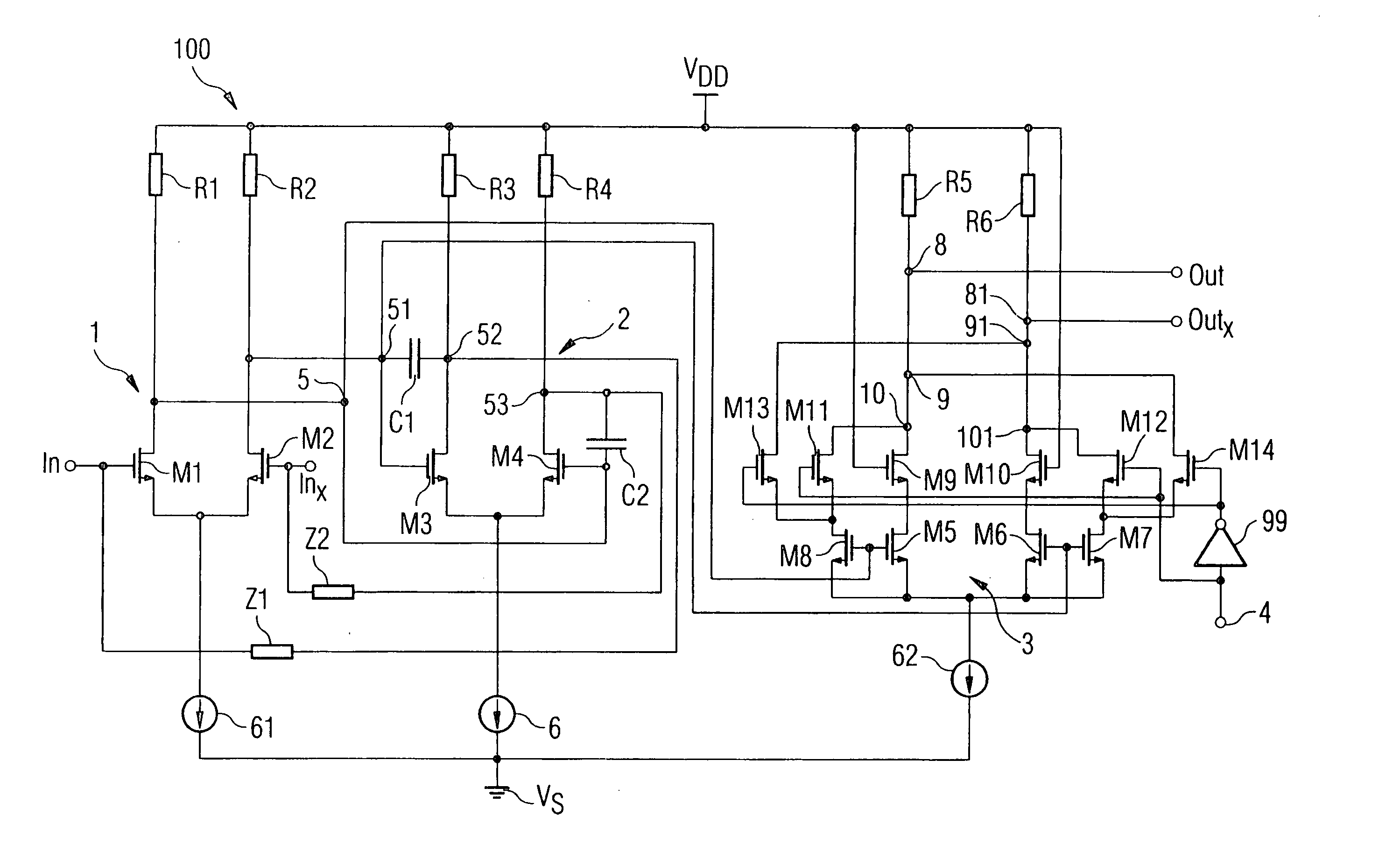
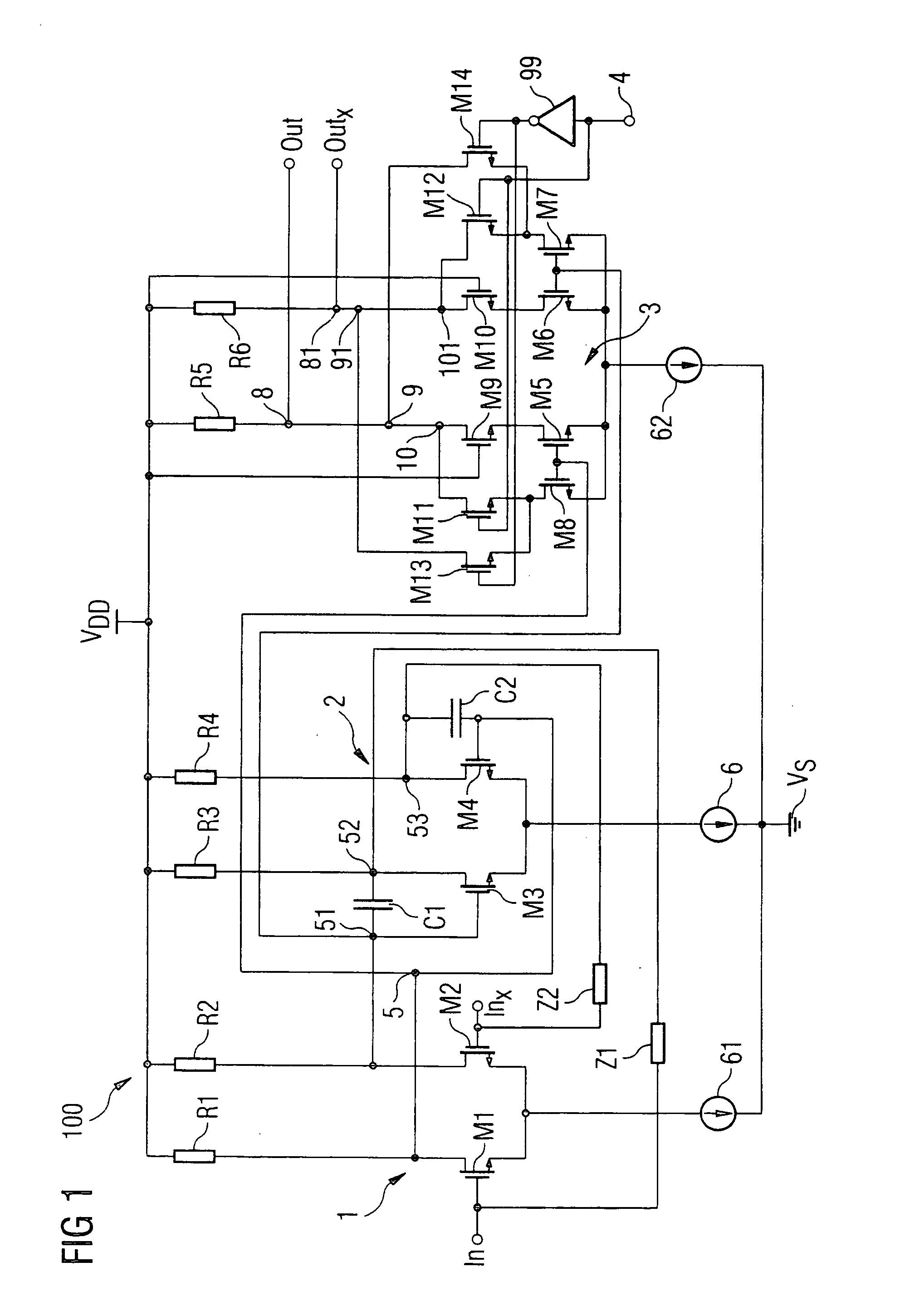
[0041]FIG. 1 illustrates a first exemplary embodiment of an inventive amplifier arrangement...


PUM


Abstract

According to one or more aspects of the present invention, an amplifier arrangement is disclosed. The arrangement comprises a first, a second and a third amplifier. The first and second amplifiers are coupled to one another such that they form a negative feedback loop. In addition, an output node of the first amplifier is connected to a signal input of the third amplifier. An output node of the third amplifier circuit forms the amplifier output of the amplifier arrangement. In addition, the third amplifier circuit is designed for switchably changing its gain on the basis of a signal at an actuating input of the amplifier arrangement.

Description

REFERENCE TO RELATED APPLICATIONS [0001] This application claims the benefit of the priority dates of German applications DE 10 2004 047 641.1, filed on Sep. 30, 2004; DE 10 2004 050 643.4 filed Oct. 18, 2004; DE 10 2005 041 318.8 filed Aug. 31, 2005; and U.S. patent application Ser. No. ______, (EHFP209US) Filed Sep. 23, 2005 entitled “Amplifier Arrangement Having An Adjustable Gain, And Use Thereof”, the contents of which are herein incorporated by reference in their entirety.FIELD OF THE INVENTION [0002] One or more aspects of the present invention relate to an amplifier arrangement having an adjustable gain, and to a use for such an amplifier arrangement. BACKGROUND OF THE INVENTION [0003] In many mobile radio standards, provision is made for the level of the output signal to be altered in order to reduce influences on neighboring subscribers. This requires alteration of a gain factor for the amplifier provided for amplifying the output signal. In addition, a wide bandwidth and ...

Claims


Application Information

Patent Timeline
Patent Type & Authority Applications(United States)
IPC IPC(8): H03F3/45
CPCH03F1/34H03F3/45183H03G1/0088H03F2203/45702H03G1/0029H03F2203/45366
Inventor STOGER, CLAUSSCHELMBAUER, WERNER
Owner APPLE INC
Why Eureka
Try Eureka