Network for distributing signals to a plurality of users

a network and user technology, applied in multiplex communication, instruments, optical elements, etc., can solve problems such as electromagnetic interference, narrow band of electric cables, and becoming a bottleneck with resp

Inactive Publication Date: 2005-06-21
PIRELLI CAVI E SISTEMI SPA
View PDF17 Cites 93 Cited by
  • Summary
  • Abstract
  • Description
  • Claims
  • Application Information

AI Technical Summary

Benefits of technology

[0094]This advantageously allows facilitating the passage of at least one of the two en

Problems solved by technology

Nevertheless, electric cables have a relatively narrow band, and they are becoming a bottleneck with respect to, the band of signals to be transmitted.
Moreover, they present problems of electromagnetic interferences, of impedance matching, and they are difficult to be introduced into the appropriate raceways of a building since they are stiff.
In addition, being bulky, they significantly reduce thee number of cables that can be inserted into a raceway.
Moreover, due to electr

Method used


Image

  • Network for distributing signals to a plurality of users
  • Network for distributing signals to a plurality of users
  • Network for distributing signals to a plurality of users

Examples


Embodiment Construction

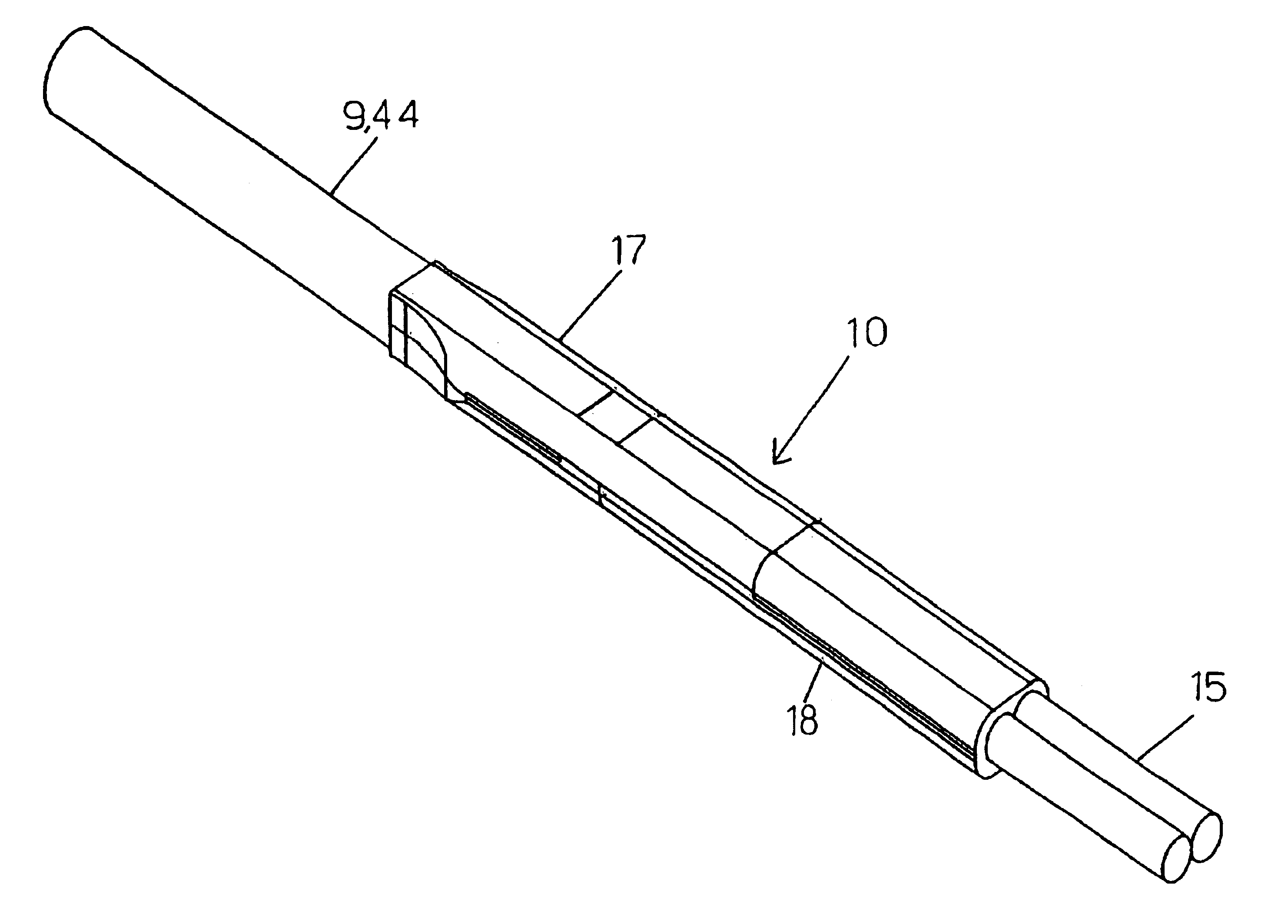
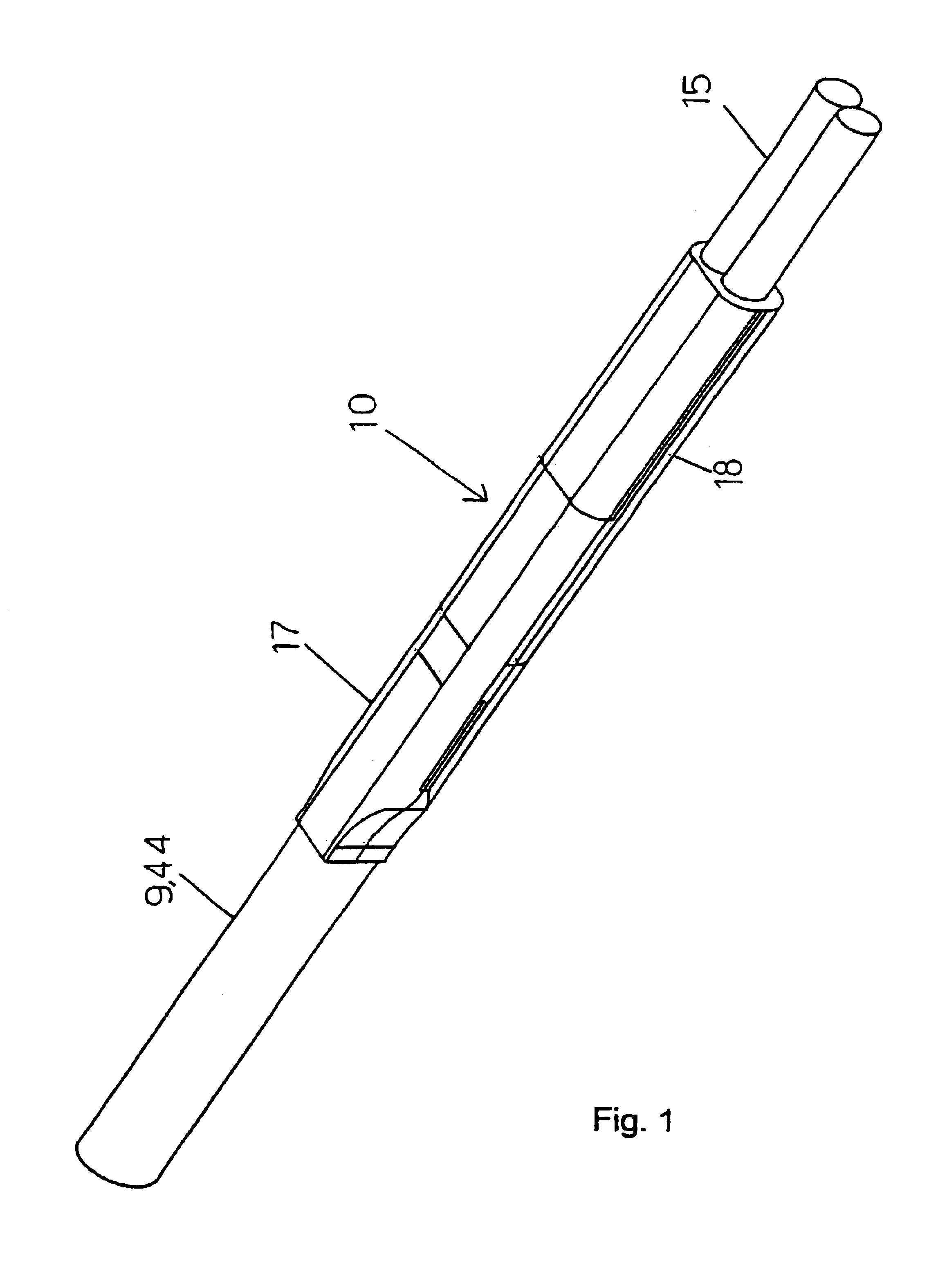
[0105]FIG. 1 shows an embodiment of an electrically terminated optical cable 1 that can be used on a distribution network 100 of the invention. It comprises an optical cable 9 having two ends and an opto-electronic end portion 10 permanently connected to one of the two ends.

[0106]In the embodiment shown, the optical cable 9 comprises two single-mode optical fibres (not shown), a plastic coating to cover both fibres, and an outer plastic sheath.

[0107]Each optical fibre is of the SMR model produced by the manufacturing firm FIBRE OTTICHE SUD F.O.S. S.p.A., has a core, a cladding with an outer diameter equal to 125 μm, and an outer acrylate coating with outer diameter of 250 μm. In addition, each fibre has a nominal attenuation equal to 0.2 dB / Km.

[0108]Moreover, the optical cable 9 comprises a plurality of longitudinal yarns made of Kevlar™ (not shown) that are flexible and tensile resistant.

[0109]Said Kevlar™ yarns are arranged between the plastic coating of the two optical fibres and...


PUM


Abstract

A network for distributing signals to a plurality of user apparatuses having a distribution unit with a plurality of ports, and a plurality of optical-fiber cables connected to the ports and suitable to make the plurality of ports of the distribution unit communicate with the plurality of user apparatuses. At least one of the plurality of optical-fiber cables is an electrically terminated optical cable having an optical cable with a single-mode optical fiber and an opto-electronic end portion mechanically and permanently connected to an end of the optical cable, and the opto-electronic end portion has an opto-electronic conversion device having an optic port optically aligned with and mechanically connected to, an end of the single-mode optical fiber.

Description

CROSS REFERENCE TO RELATED APPLICATIONS[0001]This application is a national phase application based on PCT / EP00 / 13368, filed Dec. 27, 2000, the contents of which are incorporated herein by reference, and claims the priority of European patent application No. 99830829.0, filed Dec. 31, 1999, and the benefit of U.S. Provisional Application No. 60 / 181,078, filed Feb. 8, 2000, the contents of which are incorporated herein by reference.BACKGROUND OF THE INVENTION[0002]1. Field of the Invention[0003]The present invention relates to a network for distributing signals to a plurality of users, and to a method for installing said network into a building.[0004]2. Description of the Related Art[0005]Currently, in the telecommunication field optical technology is mainly used for long-distance transmission of optical signals using the known properties of wide band provided by optical fibres. On the contrary, the most used technology for distributing signals to a plurality of users (such as for ex...

Claims


Application Information

Patent Timeline
IPC IPC(8): G02B6/42H04B10/207G02B6/38H04B10/272
CPCH04B10/272G02B6/4246G02B6/3861G02B6/3878G02B6/3887G02B6/4225G02B6/4249G02B6/4204G02B6/424G02B6/4244G02B6/4245G02B6/3889G02B6/3888
Inventor RAVASIO, GIUSEPPEOLIVETI, GUIDOZAMMARCHI, CLAUDIO
Owner PIRELLI CAVI E SISTEMI SPA
Why Eureka
Try Eureka