
Auto skew alignment of high-speed differential eye diagrams

a high-speed differential and eye diagram technology, applied in the field of high-speed differential eye diagram auto-skew alignment, can solve the problem and achieve the effect of limited accuracy of optimized skew value and minimal figure of meri

Inactive Publication Date: 2005-06-21
AGILENT TECH INC
View PDF3 Cites 34 Cited by
  • Summary
  • Abstract
  • Description
  • Claims
  • Application Information

AI Technical Summary

Benefits of technology

The present invention is a system and method for automatically aligning the timing of high-speed signals with differential timing skew. It uses a figure of merit containing time integrals of mathematical functions to calculate an optimized skew value that minimizes the figure of merit. The calculations are performed over a random time interval including at least two consecutive bit periods of the signals. The accuracy of the optimized skew value is limited only by hardware skew resolution. The invention has the technical effect of improving the accuracy and reliability of signal timing in high-speed data transmission systems.

Problems solved by technology

The accuracy of the optimized skew value is limited only by hardware skew resolution, which in present implementations is less than or equal to one picosecond.

Method used


Image

  • Auto skew alignment of high-speed differential eye diagrams
  • Auto skew alignment of high-speed differential eye diagrams
  • Auto skew alignment of high-speed differential eye diagrams

Examples


Embodiment Construction

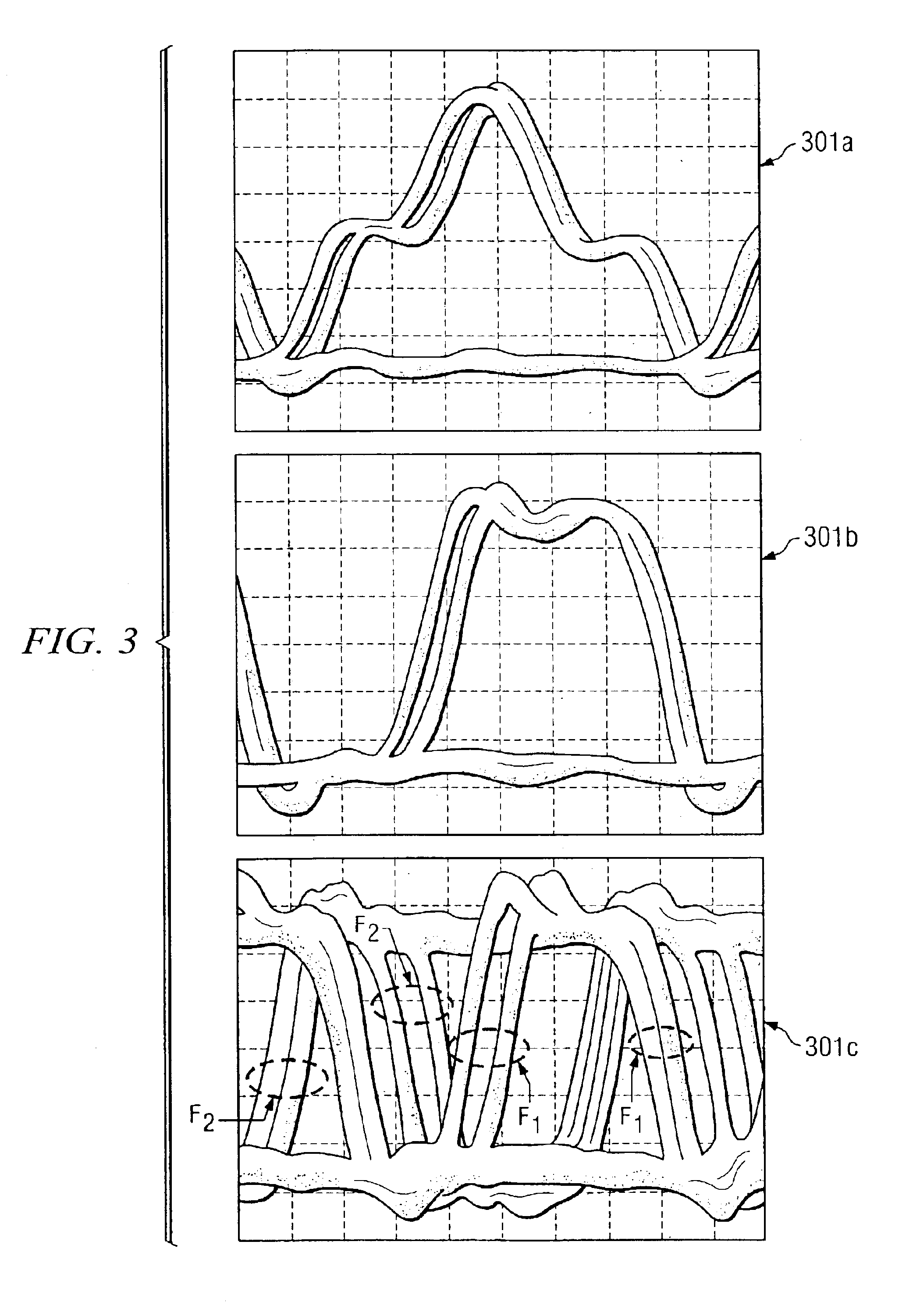
[0024]A method in accordance with embodiments of the present invention is based on the integral addition of the two differential signals. An optimized value of skew ts is calculated, such that figure of merit

FOM=(∫|F1(t1)+F2(t2+ts)|dt) / (∫|F1(t1)|dt+∫|F2(t2+ts)|dt)  (5)

reaches a minimum, which occurs when ts=t1−t2, which accordingly becomes the optimized skew value. Since the method uses integration over a wide time duration, immunity to jitter and noise is greatly enhanced. If ts=t1−t2+Δt, then when Δt approaches zero, FOM becomes

FOM=|Δt|(∫|F1′(t)|dt) / (∫|F1(t)|dt+∫|F2(t)|dt).  (6)

[0025]Thus, when Δt approaches zero, FOM reaches a minimum as well, limited only by amplitude noise, because jitter has been minimized by integration. For the method to work optimally, the time derivative F1′(t) of signal F1(t) should be non-zero. In other words, the range of acquired data should include at least one edge slope of waveform F1(t). FOM does not need any detailed information regarding edges, b...


PUM


Abstract

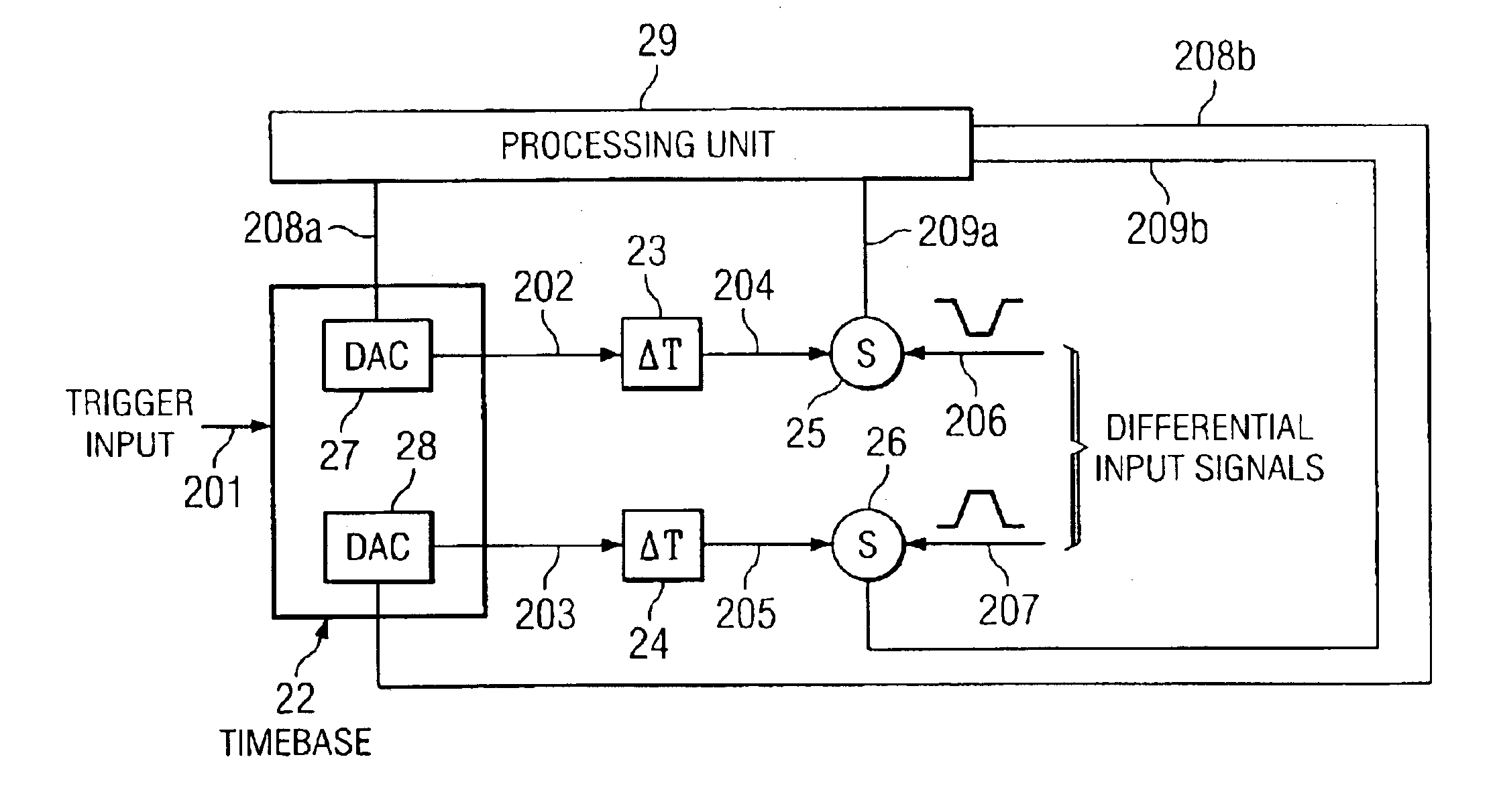
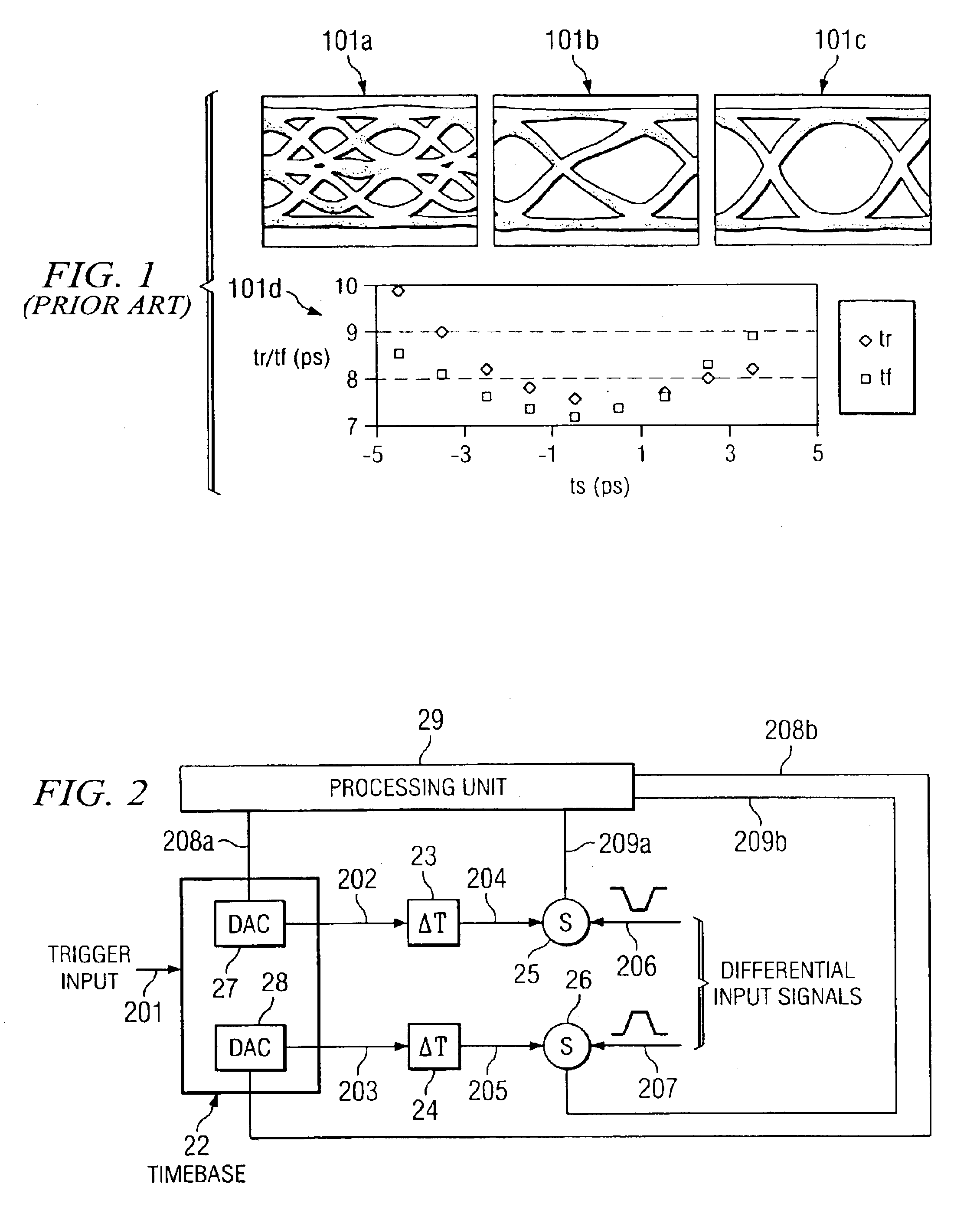
Auto-skew alignment of high-speed eye diagrams of a pair of differential signals defines a figure of merit containing time integrals of mathematical functions dependent on magnitudes of the differential signals and related skew, then calculating an optimized skew value that minimizes the figure of merit. Optimally integrals are performed over a random time interval including at least two consecutive bit periods of the differential signals. Calculations include coarse search for optimum skew and fine search using an adaptively decreasing fine skew interval. Data acquisition and control hardware includes paired independent skew circuits and paired sampling circuits coupled to a timebase generator and a processing unit, which performs calculations in accordance with an auto-deskew algorithm. The accuracy of the optimized skew value is limited only by hardware skew resolution which in present implementations is less than or equal to one picosecond.

Description

CROSS-REFERENCE TO RELATED APPLICATIONS[0001]This application is related to co-pending and commonly assigned U.S. patent application Ser. No. 10 / 387,791 entitled “VARIABLE DATA RATE BIT ERROR MEASUREMENTS USING BIT REPLICATION,” the disclosure of which is hereby incorporated herein by reference.TECHNICAL FIELD[0002]The invention relates to instrumentation and methods for performance measurement of high data rate digital communications systems and particularly to auto-skew alignment of high-speed differential eye diagrams.BACKGROUND OF THE INVENTION[0003]The increased deployment of Gigabit differential signals in IC components and systems for high-speed telecommunication applications presents challenges in signal analysis and measurement. One such challenge resides in skew alignment of the high-speed differential signals as represented by differential eye diagrams. Today's telecom systems are designed to move large amounts of data at bit rates that far exceed 1 Gbit / sec, with signal ...

Claims


Application Information

Patent Timeline
Patent Type & Authority Patents(United States)
IPC IPC(8): G01R13/00G01R13/02G06K9/00H04L25/02H04L25/14
CPCG01R13/029H04L25/14G06K9/00536H04L25/0272G06F2218/12
Inventor FERNANDO, CHENJING
Owner AGILENT TECH INC
Learn More