Portable computer system for indicating power-on self-test state on LED indicator

a computer system and led indicator technology, applied in error detection/correction, program control, instruments, etc., can solve the problems of inability to display post codes to users, difficult to identify the error occurred in the computer system, and the post card cannot be plugged into the portable computer system

Inactive Publication Date: 2005-06-21
SAMSUNG ELECTRONICS CO LTD
View PDF21 Cites 43 Cited by
  • Summary
  • Abstract
  • Description
  • Claims
  • Application Information

AI Technical Summary

Benefits of technology

[0015]It is still yet another object to provide a quick and easy way of monitoring the POST state without extra attachments to a portable computer system.
[0016]It is another object t

Problems solved by technology

For example, if the docking station is not coupled to the portable computer system, the POST card cannot be plugged in the portable computer syste

Method used


Image

  • Portable computer system for indicating power-on self-test state on LED indicator
  • Portable computer system for indicating power-on self-test state on LED indicator
  • Portable computer system for indicating power-on self-test state on LED indicator

Examples


first embodiment

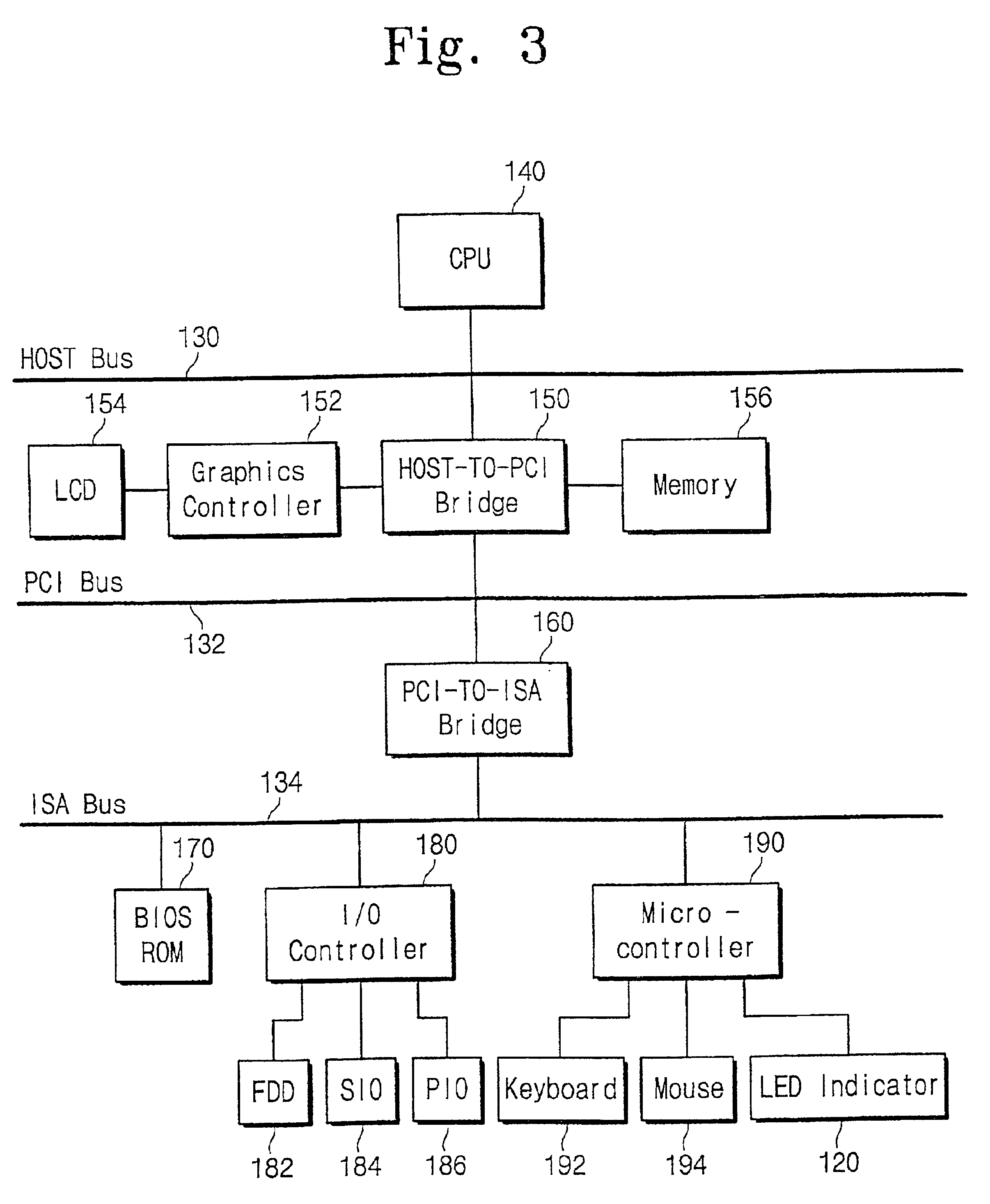
[0030]FIG. 3 is a block diagram for illustrating a structure of a portable computer system according to the present invention. Referring to FIG. 3, the computer system has a central processing unit (CPU) 140 coupled to a HOST bus 130, a HOST-TO-PCI bridge controller 150 coupled between the HOST bus 130 and a PCI (Peripheral Component Interconnection) bus 132, and a PCI-TO-ISA bridge controller 160 coupled between the PCI bus 132 and an ISA bus 134.

[0031]To the HOST-TO-PCI bridge controller 150, a graphics controller 152 and a memory 156 are coupled, respectively. The graphics controller 152 is coupled to a liquid crystal display (LCD) 154. To the ISA bus 134, a BIOS ROM 170, an I / O controller 180 and a micro-controller 190 are coupled, respectively. The I / O controller 180 is coupled to a floppy disk drive (FDD) 182, a serial input output (SIO) port 184 and a parallel input output (PIO) port 186, respectively. In addition, the micro-controller 190 is coupled to a keyboard 192, a mous...

second embodiment

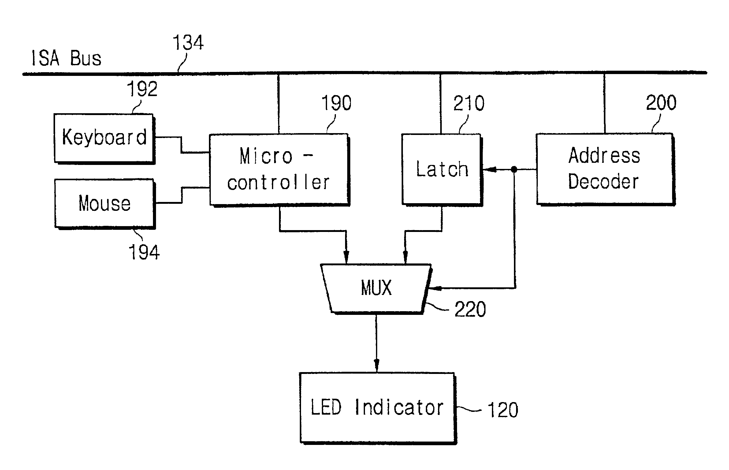
[0039]FIG. 6 is a block diagram for illustrating a structure of a circuit to control the LED indicator 120 according to the present invention. The circuit of FIG. 7 that modifies the circuit of FIG. 6, is capable of indicating POST codes to the LED indicator 120, selectively. In FIGS. 6 and 7, the same parts as those shown in FIG. 3 are represented with like reference numerals and to avoid description duplication.

[0040]Referring to FIG. 6, the portable computer system has an address decoder 200 coupled to an ISA bus 134, a latch 210 and a multiplexer (MUX) 220, to indicate POST codes to the LED indicator 120.

[0041]The address decoder 200 coupled to an address bus of the ISA bus 134 decodes an address signal from the ISA bus 134. The address decoder 200 enables the latch 210 when an address signal is loaded to the I / O port 80h. The latch 210 coupled to a data bus of the ISA bus 134 latches a data from the ISA bus 134, when the latch 210 is enabled by the address decoder 200. The mult...


PUM


Abstract

A portable computer system has a light emitting diode (LED) indicator including multiple LEDs to display a power-on self-test (POST) state and an operating state of the computer system. When the portable computer system performs a POST process during system boot, the LEDs of the LED indicator are lighted in response to each step of the POST process. If any error is detected in the POST process, the POST process is stopped with lighting LEDs. The lighting state of the LED indicator indicates where the error has occurred in the computer system, so that a user can verify which element of the computer system has an error, without additionally adding a POST card to the computer system.

Description

CLAIM OF PRIORITY[0001]This application makes reference to, incorporates the same herein, and claims all benefits accruing under 35 U.S.C. § 119 from my application PORTABLE COMPUTER SYSTEM FOR INDICATING POWER-ON SELF-TEST STATE ON LED INDICATOR filed with the Korean Industrial Property Office on 16 Jul. 1999 and there duly assigned Serial No. 28925 / 1999.BACKGROUND OF THE INVENTION[0002]1. Field of the Invention[0003]The present invention relates to a data processing system, and more particularly to a portable computer system with a diagnostic routine.[0004]2. Related Art[0005]When a computer system is first turned on, a Basic Input / Output System (BIOS) is enabled. A BIOS program is a set of programs usually stored permanently in a read only memory (ROM) that provides the most basic control and management of the computer's hardware. The first job of a BIOS program is to initialize and to configure the computer hardware when the user turns on the computer (i.e., system boot). The BI...

Claims


Application Information

Patent Timeline
IPC IPC(8): G06F11/00G06F11/22G06F11/32
CPCG06F11/326G06F11/22
Inventor PARK, JANG-HOKIM, DONG-WOOK
Owner SAMSUNG ELECTRONICS CO LTD
Why Eureka
Try Eureka