

Electrical tool with a quick-action clamping device
- Summary
- Abstract
- Description
- Claims
- Application Information
AI Technical Summary
Benefits of technology
Problems solved by technology
Method used
Image

Examples
Embodiment Construction
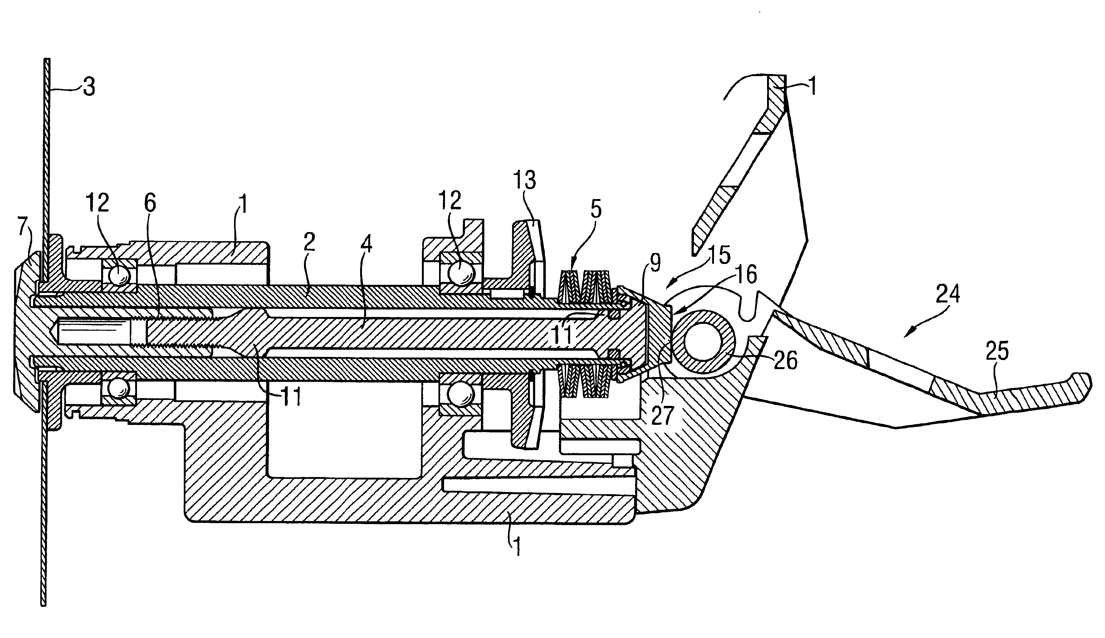
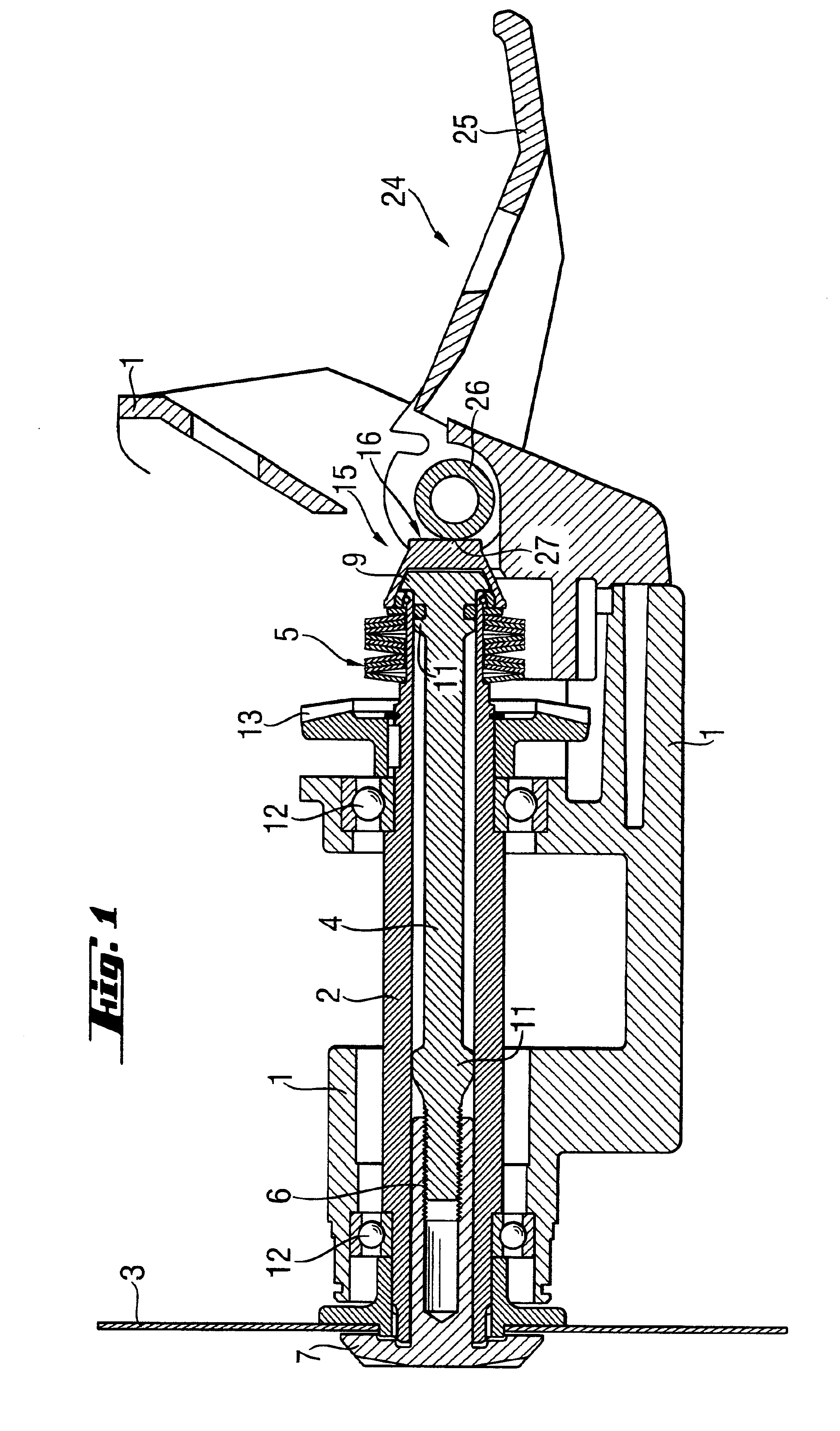
[0033]FIGS. 1-3 show a portion of an electrical tool, in particular a circular saw, with a quick-action clamping device according to the present invention which is arranged in the housing 1 of the tool.
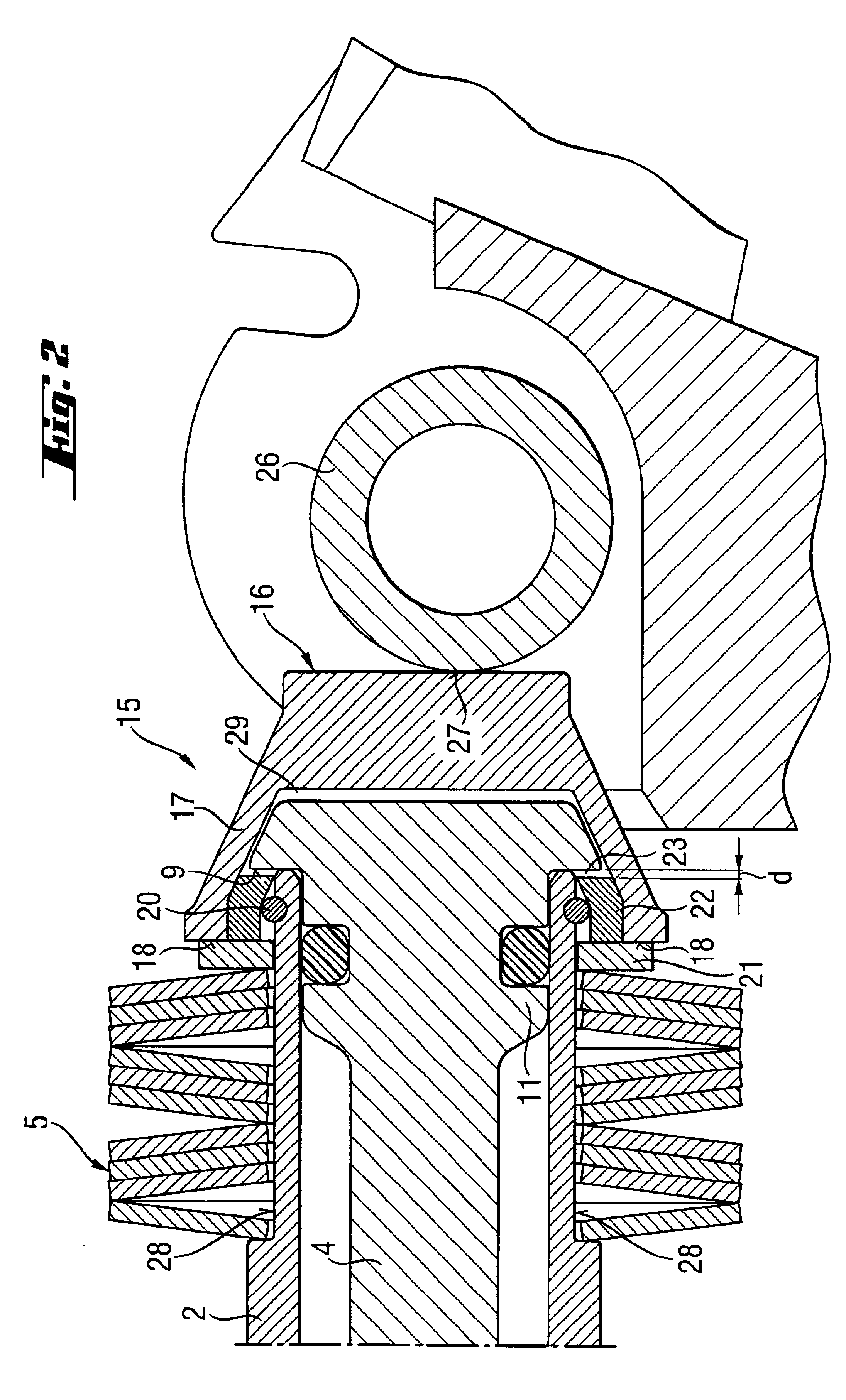
[0034]The quick-action clamping device has a motor-driven hollow spindle 2 and a clamping spindle 4 which is displaceably arranged in the hollow spindle 2 coaxially therewith. An elastic member 5 displaces the clamping spindle 4 relative to the hollow spindle 2 between a clamping position, which is shown in FIG. 3, and an exchange position shown in FIGS. 1-2. In the clamping position of the quick-action clamping device, a working tool 3 in clamped between a clamping flange 7, which is provided at a working tool-side of the clamping spindle 4, and the hollow spindle 2. The quick-action clamping device further includes a compensator 15 having a stop element and a transmission element and which interrupts the action of the elastic member 5 on the clamping spindle 4.
[0035]At its working t...
PUM
| Property | Measurement | Unit |
|---|---|---|
| Elasticity | aaaaa | aaaaa |
Abstract
Description
Claims
Application Information